
Systems and methods that employ object recognition

a technology of object recognition and object detection, applied in the field of illumination devices, can solve the problems of unsatisfactory solutions for pir sensors, pir sensors are not ideal solutions, and pir sensors are typically not able to detect objects at ambient temperatur

Active Publication Date: 2013-09-05
EXPRESS IMAGING SYST
View PDF19 Cites 87 Cited by
  • Summary
  • Abstract
  • Description
  • Claims
  • Application Information

AI Technical Summary

Benefits of technology

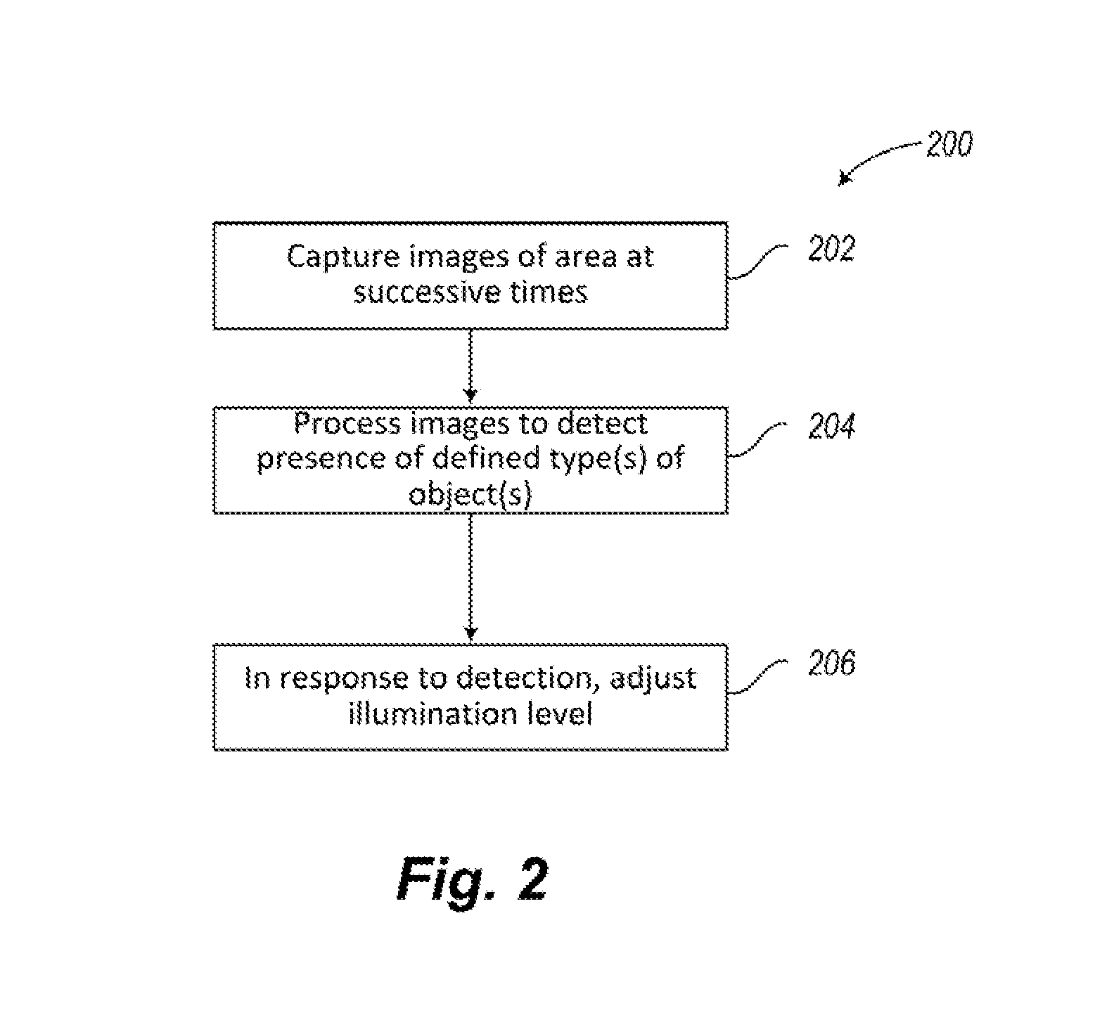
The patent describes an illumination system that uses a non-Passive Infrared (non-PIR) imager to detect movement in an area and adjust the level of illumination accordingly. The system can detect the presence of a body in the area and adjust the illumination level accordingly. The non-PIR imager can capture images at different times and the system can adjust the illumination level based on the difference in image data between the two images. The system can also use a photosensor or a clock to determine the level of ambient light and adjust the illumination level accordingly. The patent also describes a method for controlling the light source based on the detected movement in the area. The technical effect of this patent is to provide an improved illumination system that can automatically adjust the level of illumination based on the detected movement in the area, making it more efficient and effective.

Problems solved by technology

PIR sensors, however, are not an ideal solution.
Otherwise, the benefit of using a PIR sensor to automatically control the illumination level under such circumstances would likely be diminished.
Furthermore, PIR sensors typically cannot detect objects that are at ambient temperature, such as a door opening for example, although such an event usually indicates the approach of a person and is desirable to detect.

Method used


Image

  • Systems and methods that employ object recognition
  • Systems and methods that employ object recognition
  • Systems and methods that employ object recognition

Examples


Embodiment Construction

[0018]In the following description, certain specific details are set forth in order to provide a thorough understanding of various disclosed embodiments. However, one skilled in the relevant art will recognize that embodiments may be practiced without one or more of these specific details, or with other methods, components, materials, etc. In other instances, well-known structures associated with luminaires and imaging devices have not been shown or described in detail to avoid unnecessarily obscuring descriptions of the embodiments.

[0019]Unless the context requires otherwise, throughout the specification and claims which follow, the word “comprise” and variations thereof, such as, “comprises” and “comprising” are to be construed in an open, inclusive sense that is as “including, but not limited to.”

[0020]Reference throughout this specification to “one embodiment” or “an embodiment” means that a particular feature, structure or characteristic described in connection with the embodim...


PUM


Abstract

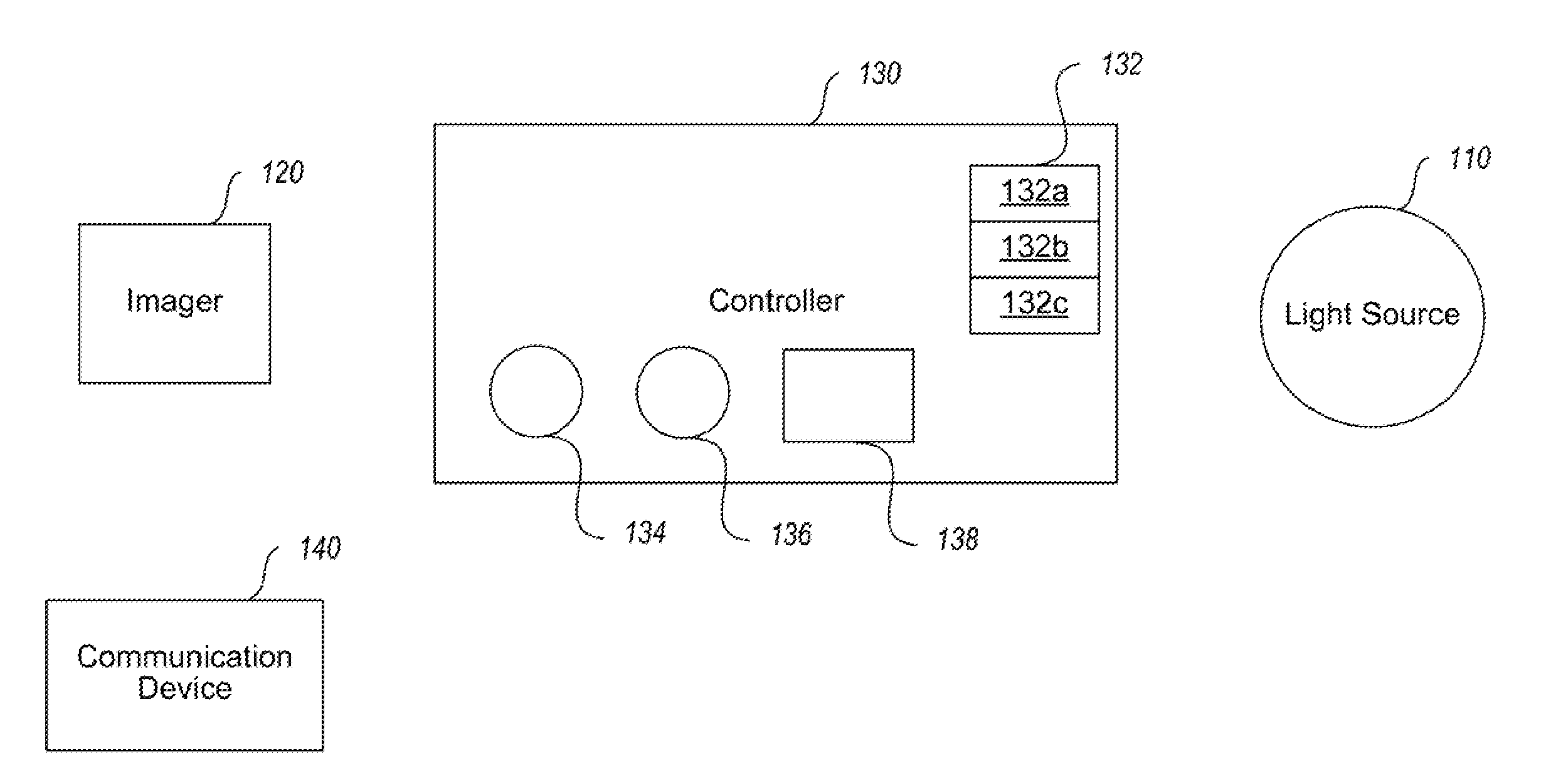
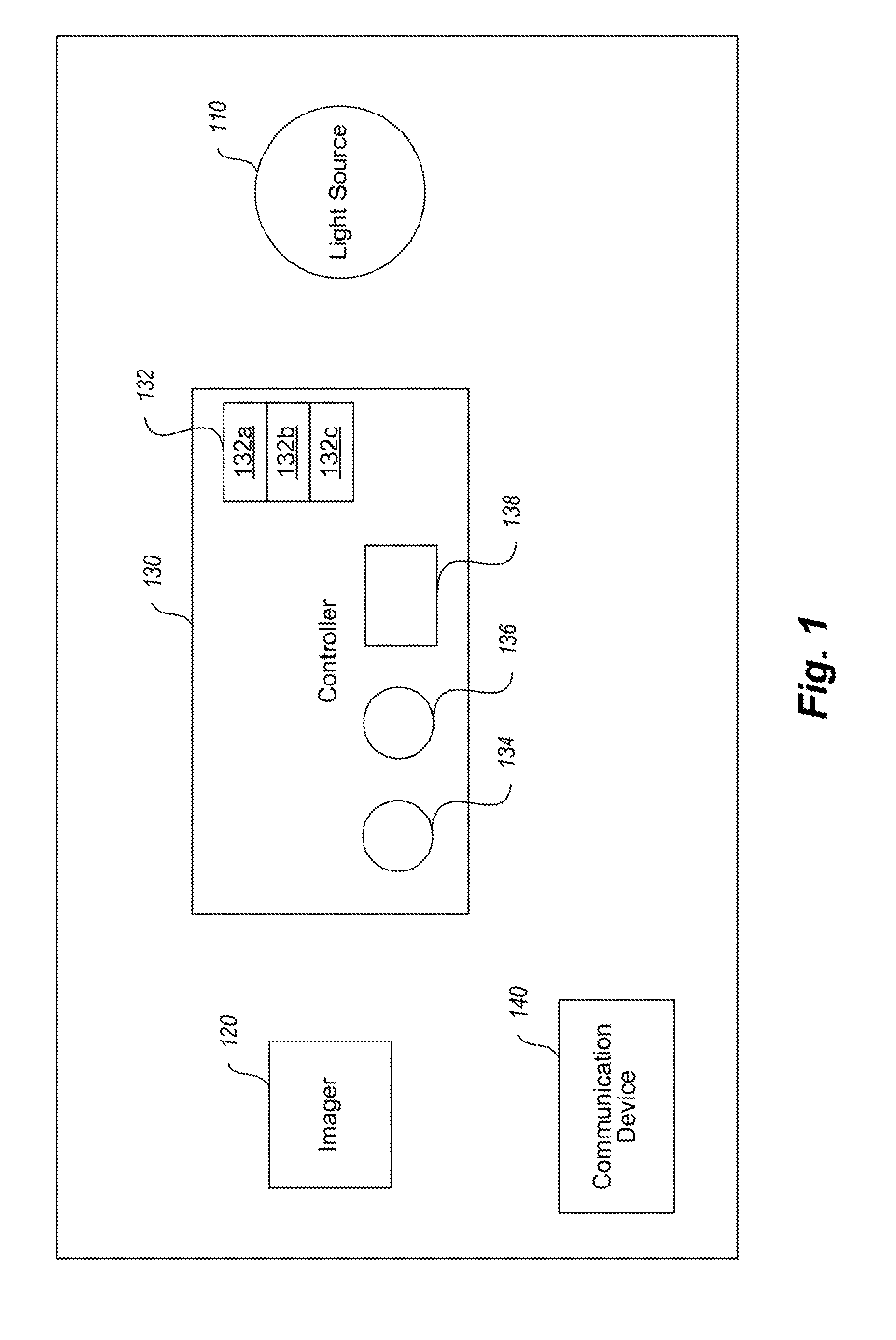
An illumination system and methods to control a light source are provided. An illumination system includes a light source, a two-dimensional non-Passive Infrared (non-PIR) imager, and a controller. The light source may provide at least two levels of illumination. The non-PIR imager images an area and to produce image data representative of images across at least part of a visible portion of an electromagnetic spectrum. The controller is communicatively coupled to receive the image data from the non-PIR imager and process the received image data to detect at least one object in the area of a defined type of object. The controller is also coupled to control operation of the light source based on, at least in part, detection of the ambient characteristic of the environment. Alternatively, one or more components of a system may be used to monitor traffic, with or without active illumination.

Description

BACKGROUND[0001]1. Technical Field[0002]The present disclosure generally relates to the field of illumination devices and, more particularly, to the control of illumination levels of illumination devices.[0003]2. Description of the Related Art[0004]Energy conservation through the efficient usage of energy has become an important topic in recent years. Efficient usage of energy can result in a multitude of benefits, including financial benefits such as cost savings and environmental benefits such as preservation of natural resources and the environment. In the context of light systems, efficient energy usage by a lighting system is perhaps most effectively accomplished by reducing the illumination level when a high illumination level is not needed. This can be achieved manually by a user of the lighting system or, more conveniently, by some sort of automatic control mechanism that adjust the illumination level according to changes in certain environmental characteristics.[0005]One co...

Claims


Application Information

Patent Timeline
Patent Type & Authority Applications(United States)
IPC IPC(8): H04N5/33H05B37/02
CPCH05B37/0227H05B37/0272H04N5/2354Y02B20/72H04N5/23254H04N5/33H05B47/19H05B47/125Y02B20/40H04N23/6811H04N23/74H04N23/20
Inventor REED, WILLIAM G.DEGRAFF, DALE H.
Owner EXPRESS IMAGING SYST
Learn More