
Wireless Power Transmission System

a power transmission system and wireless technology, applied in the direction of transformers, inductances, transportation and packaging, etc., can solve the problems of easy damage to the connector or portable electronic device, the need to form openings, and the impact of exposed connectors or even internal circuits, so as to reduce the use of connectors and improve charging convenience. convenience, cost reduction

Active Publication Date: 2013-09-05
SOFT HAPTIC TECH
View PDF17 Cites 3 Cited by
  • Summary
  • Abstract
  • Description
  • Claims
  • Application Information

AI Technical Summary

Benefits of technology

The invention provides a wireless power transmission system for electronic devices. The system uses a display device to transmit power to electronic devices, improving charging convenience, reducing costs, saving energy, and protecting the environment. The display device has a substrate and an array of electrodes on its surface. When the substrate emits an electric power signal, it couples to the electronic device, providing energy for its operation. Additionally, the invention provides an array display device with a substrate and array of electrodes that work together to transmit power to electronic devices.

Problems solved by technology

Portable electronic devices in the prior art are electrically connected with batteries or charging adaptor through connectors to perform charging, which results in that openings must be formed in the housings of the portable electronic devices for the connectors.
The exposed connector or even an internal circuit may be affected by moisture through the opening formed in the housing since moisture is known to cause malfunction of electronic components.
Furthermore, it is easy for a connector or a portable electronic device to be damaged when users plug or unplug the connector.
However, one major obstacle to deploy the electronic label is the source of electric power.
When the design of the pen is of an active type, how to achieve both a streamlined appearance and a power source for long-term usage is also an important issue while promoting stylus input.

Method used


Image

  • Wireless Power Transmission System
  • Wireless Power Transmission System
  • Wireless Power Transmission System

Examples


Embodiment Construction

[0031]The present invention will be apparent from the following detailed description proceeded with reference to the accompanying drawings. Wherein the same reference relates to the same element.

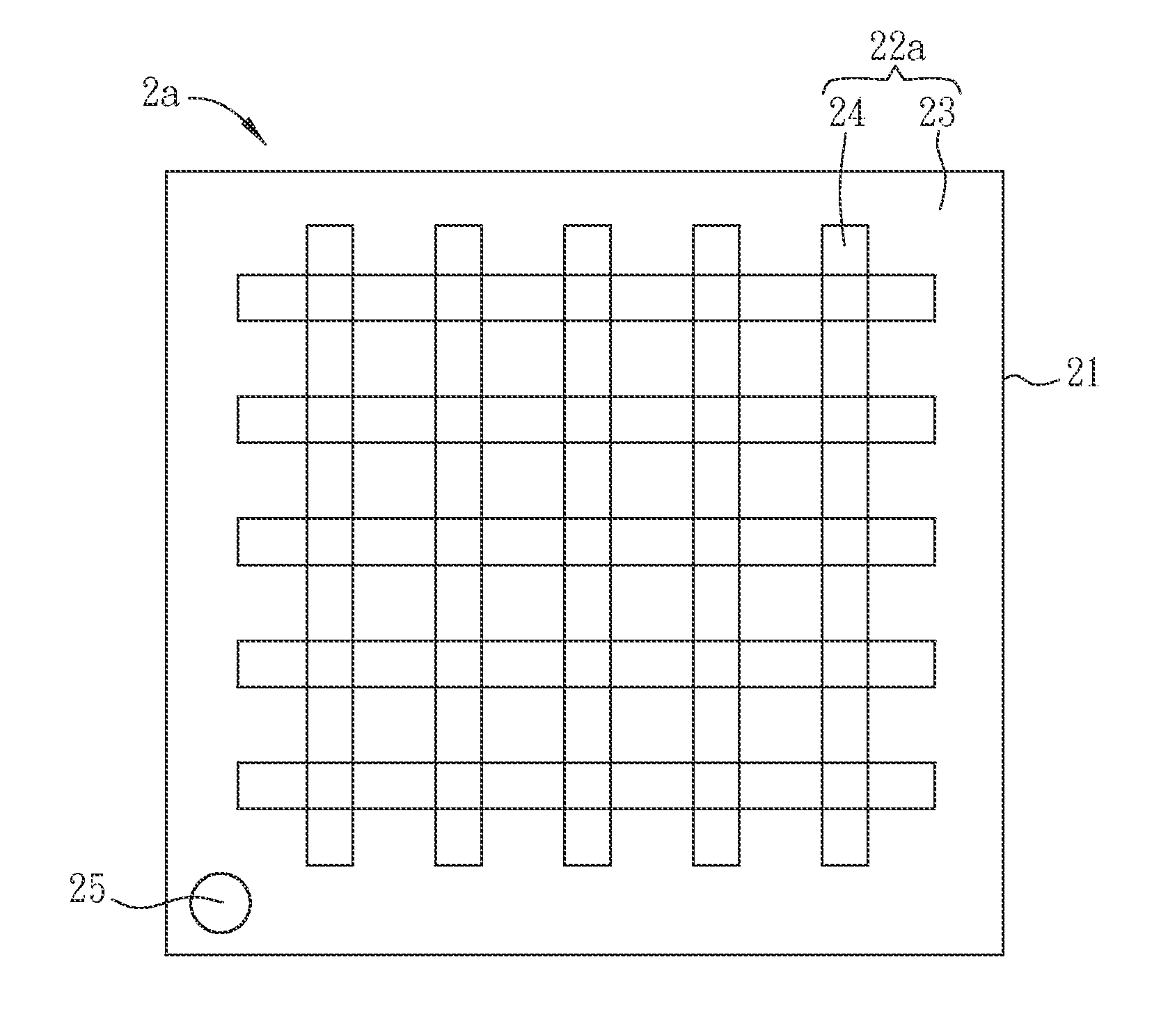
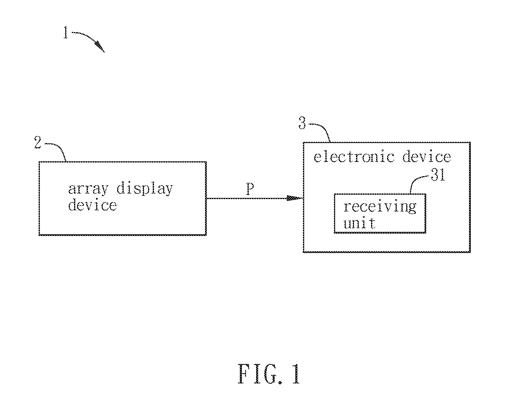
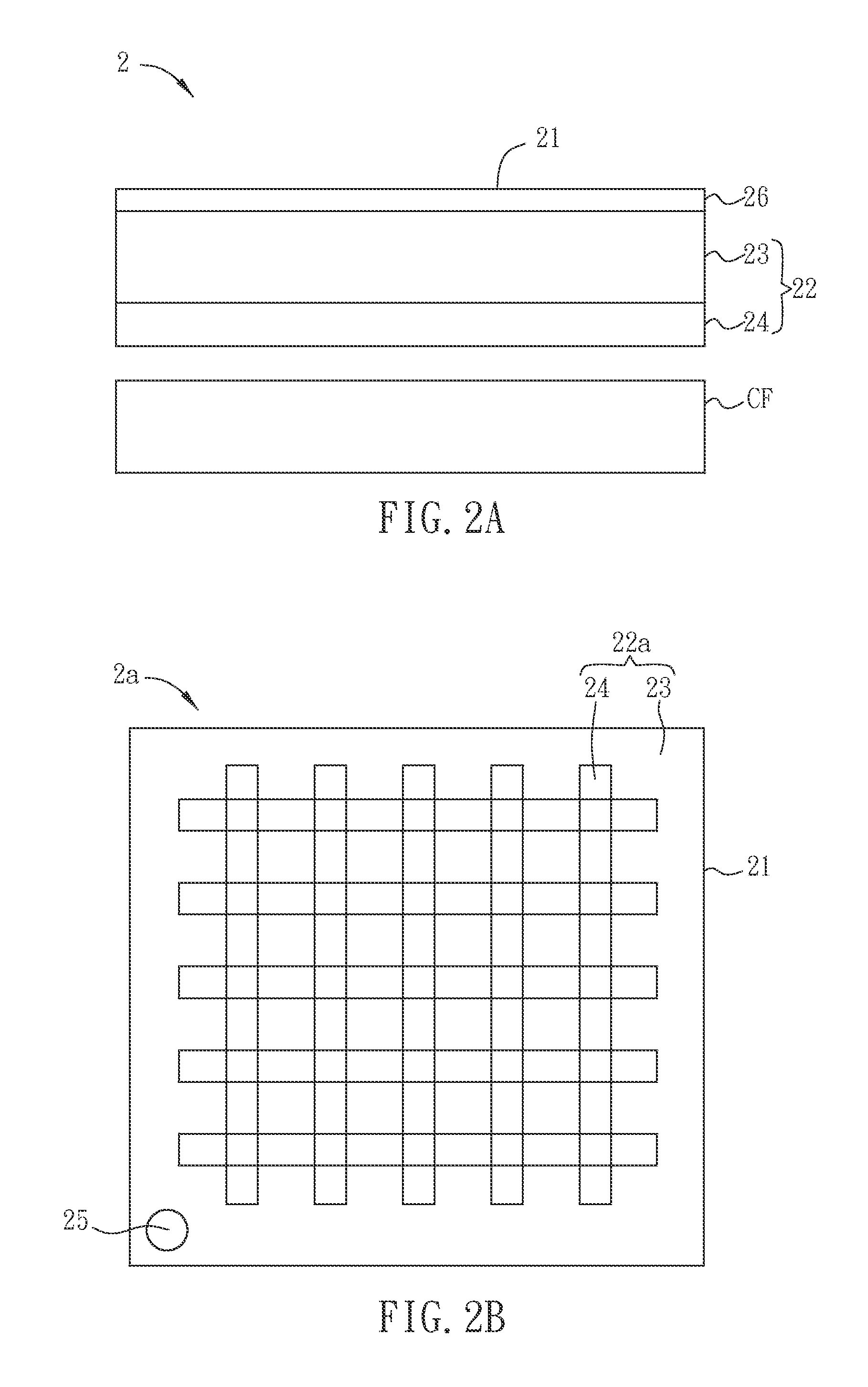
[0032]FIG. 1 is a schematic block diagram showing a wireless power transmission system 1 according to a preferred embodiment of the invention. The wireless power transmission system 1 includes an array display device 2 and an electronic device 3. The array display device 2 and the electronic device 3 are coupled via, for example, capacitive or inductive coupling so that an electric power signal P can be transmitted from the array display device 2 to the electronic device 3 in a non-contact connection manner. The electric power signal P provides the energy for the operation of electronic device 3. Therefore, it is called a wireless power transmission. In the present embodiment, the array display device 2 is, for example, a liquid-crystal display device, an organic light-emitting diode display...


PUM


Abstract

A wireless power transmission system includes an electronic device and an array display device. The array display device includes a display surface and an array substrate. The array substrate has a substrate and an array which is disposed at one side of the substrate. The array substrate emits an electric power signal coupled to the electronic device from the display surface. The electronic device manages the electric power signal for operation.

Description

CROSS REFERENCE TO RELATED APPLICATIONS[0001]This Non-provisional application claims priority under 35 U.S.C. §119(a) on Patent Application No(s). 101107090 filed in Taiwan, Republic of China on Mar. 2, 2012, the entire contents of which are hereby incorporated by reference.BACKGROUND OF THE INVENTION[0002]1. Field of Invention[0003]The invention relates to a wireless power transmission system.[0004]2. Related Art[0005]In recent years, touch panels have been gradually and widely used in consumer electronic devices such as smart phones, digital cameras, MP3 players, PDAs, GPS, hand-held PC, and ultra mobile PC (UMPC). A touch panel is combined with a display to form a touch-sensitive display device.[0006]On the other hand, in view of the convenience of portable electronic devices, charging devices for portable electronic devices, such as solar charging devices for Bluetooth earphones and solar charging devices for mobile phones, have been developed. Portable electronic devices in the...

Claims


Application Information

Patent Timeline
Patent Type & Authority Applications(United States)
IPC IPC(8): H02J7/00H04B5/00
CPCH02J7/025H02J7/0042H04B5/0012H04B5/0037H02J5/005H04B5/0075H02J50/402H02J50/05H02J50/10H04B5/22H04B5/24H04B5/79
Inventor TSAI, HSIUNG-KUANG
Owner SOFT HAPTIC TECH
Learn More