
Electric power control device and electric power control system using same

a technology of electric power control and control device, which is applied in the direction of ac network with energy trading/transmission rights, relays, dc circuits with constant current supply, etc., can solve the problems of small difference, difficult implementation, and increased cost of data management, so as to reduce the economic damage of each consumer

Inactive Publication Date: 2013-09-05
PANASONIC INTELLECTUAL PROPERTY MANAGEMENT CO LTD
View PDF2 Cites 35 Cited by
  • Summary
  • Abstract
  • Description
  • Claims
  • Application Information

AI Technical Summary

Benefits of technology

The present invention provides an electric power control device and system that can stabilize the electric power system by reducing reversed power flow and economic damage to consumers.

Problems solved by technology

That is, the management of a lot of information is needed, and therefore, there has been a problem that the cost of data management is increased.
As explained above, the technique described in the above-mentioned document has a problem that it is difficult to be implemented under conditions that there is a large number of the dispersed power sources connected to the secondary side of the pole transformer and there is a small difference between distances of cable runs in the electric power system among the adjacent dispersed power sources.
That is, because the consumer can not get paid for the amount of the surplus electricity from the electric power provider by performing the reverse power flow of the surplus electricity, such suppression causes economic damage to the consumer.
As a result, there is a problem that the operational efficiency of the dispersed power source is reduced.
Thus, it is not economical to suppress the power generation despite the state where the dispersed power source can generate power.
However, it is expected that the energy storage system is very expensive to install, and the electric power provider does not benefit much economically.
Also, it is difficult to secure a place for the installation of the energy storage system in a residential area.
Therefore, there is a high possibility that such a large energy storage system does not enable the diffusion of the dispersed power source.

Method used


Image

  • Electric power control device and electric power control system using same
  • Electric power control device and electric power control system using same
  • Electric power control device and electric power control system using same

Examples


Embodiment Construction

[0029]An electric power control device and an electric power control system using the same according to the present embodiment will be explained referring to drawings.

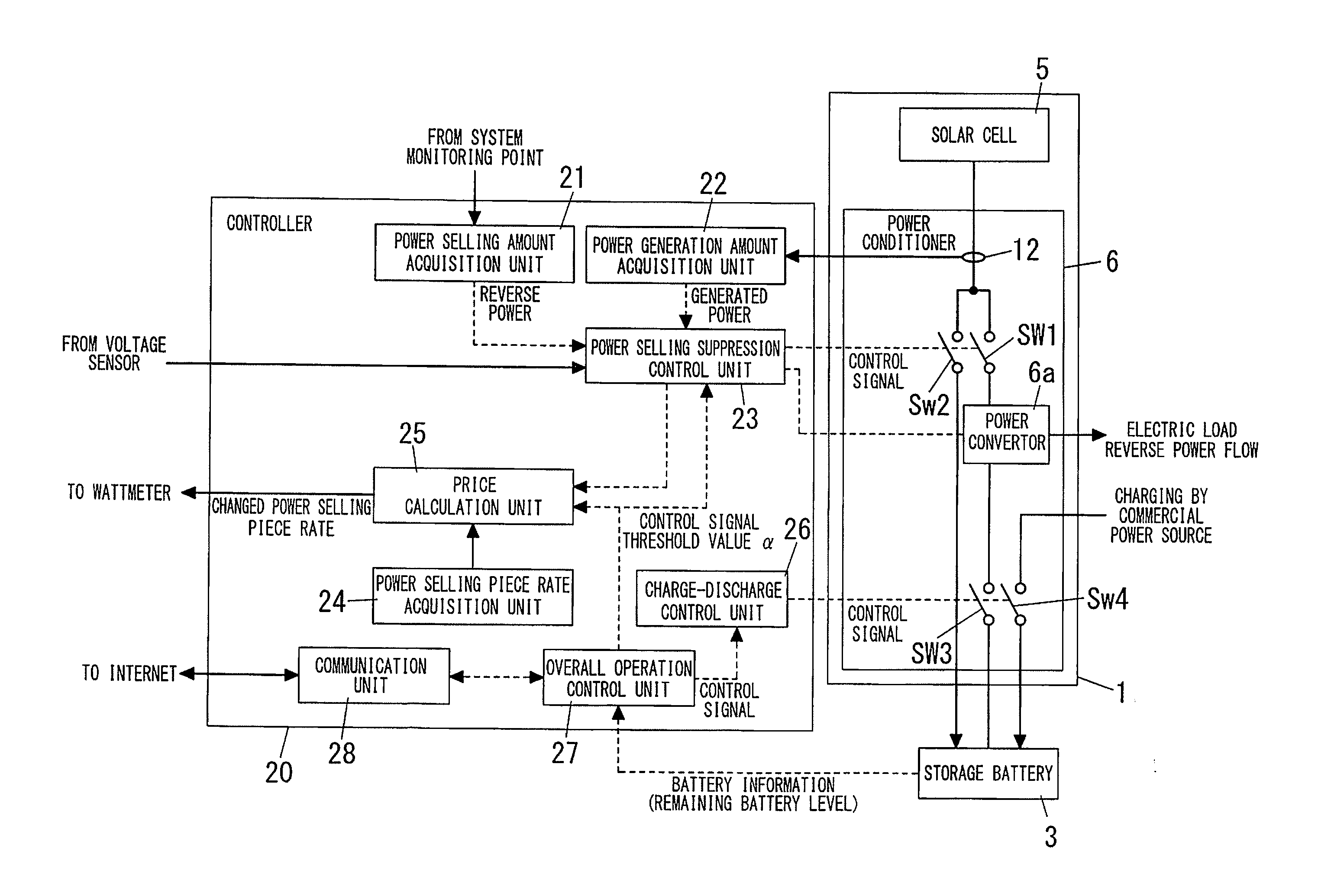
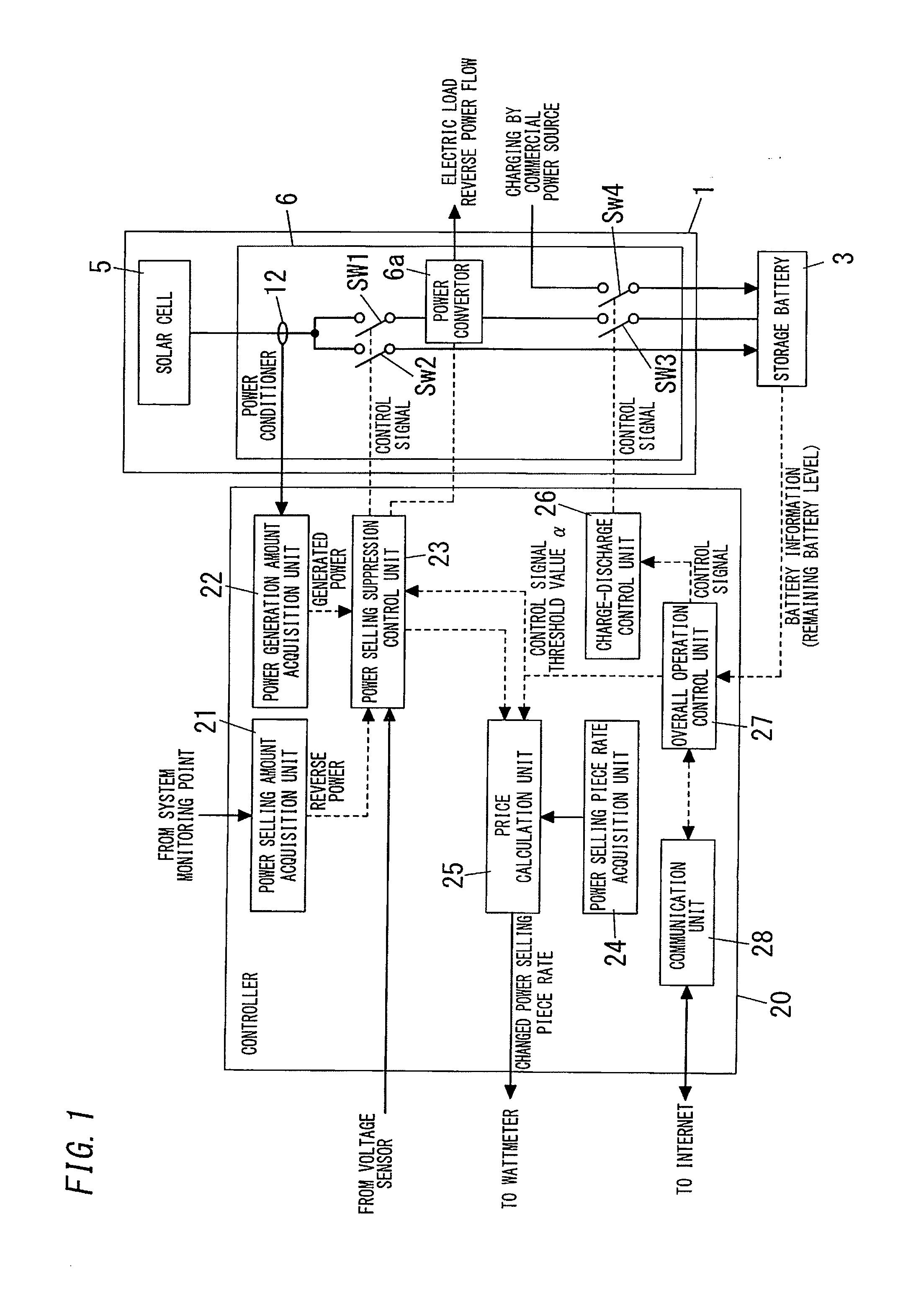
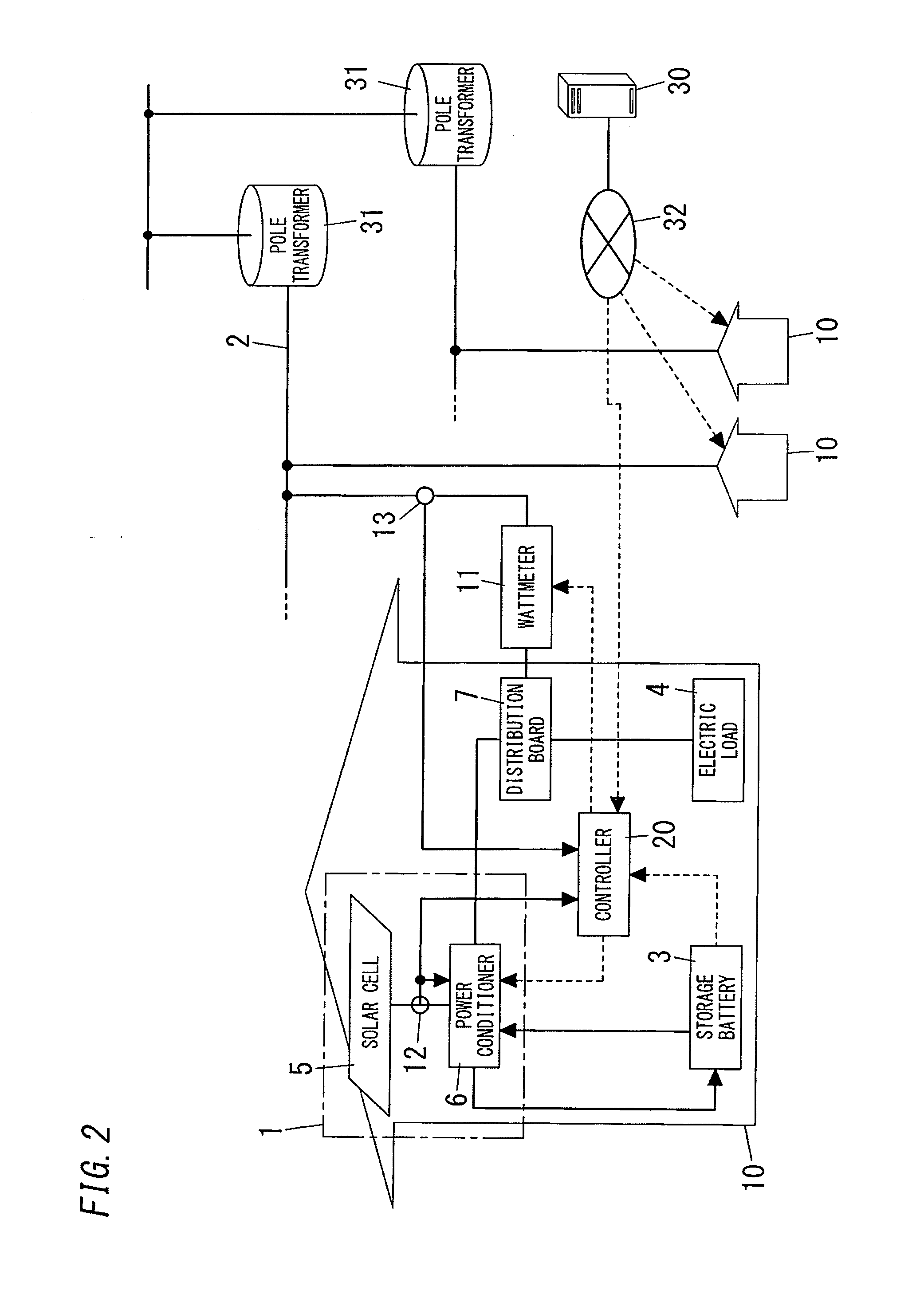
[0030]FIG. 2 shows a configuration diagram of the electric power control system. The electric power control system performs a grid connected operation of a dispersed power source 1 installed at a consumer's house 10; and an electric power system 2 of a commercial power source. Further, a storage battery 3 is provided in at least one of outside and inside of the consumer's house 10. The storage battery 3 is provided to store electricity which is not allowed to flow into the electric power system 2 by reverse power flow, among surplus electricity which is obtained by subtracting the amount consumed in an electric load 4 from the amount of electricity that has been generated at the dispersed power source 1. The storage battery 3 supplies electricity to the electric load 4, as needed.

[0031]The consumer's house 10 is connec...


PUM


Abstract

A controller installed at each consumer side comprises: a power generation amount acquisition unit acquiring the amount of electricity that has been generated in a solar cell; a power selling amount acquisition unit acquiring the amount of electricity for sale that has been allowed to flow into an electric power system by reverse power flow, among the electricity generated in the solar cell; and a power selling suppression control unit configured to set a threshold value for the amount of the electricity for sale, as proportional to the amount of the generated electricity acquired by the power generation amount acquisition unit, and configured to suppress the reverse power flow into the electric power system so that the amount of the electricity for sale is set to the threshold value or less.

Description

TECHNICAL FIELD[0001]The invention relates generally to an electric power control device and an electric power control system using the same.BACKGROUND ART[0002]Recently, a power generation device, such as a solar power generation device, a fuel cell or a wind power generation device, increasingly has been installed at electric power consumer sides, such as factories or houses. Further, a grid connected system also has been put to practical use. The grid connected system makes this kind of power generation device perform the grid connected operation with an electric power system of a commercial power source, thereby using the power generation device as a dispersed power source. In the grid connected system, surplus electricity, which is obtained by subtracting the amount consumed in a consumer side from the amount of electricity generated in the dispersed power source, is allowed to flow into the electric power system of the commercial power source by reverse power flow. Then, when ...

Claims


Application Information

Patent Timeline
IPC IPC(8): H02J1/00
CPCH02J3/008H02J3/383Y02E10/563H02J13/0079H02J1/00Y02B10/14Y04S50/10H02J2310/12H02J2300/24H02J3/381H02J13/00004H02J13/00028H02J13/00034Y02B10/10Y02E10/56Y04S10/123Y02P80/14Y02E40/70
Inventor BABA, AKIRATAKEHARA, KIYOTAKANAKAKITA, KENJIHIBIYA, SHINPEI
Owner PANASONIC INTELLECTUAL PROPERTY MANAGEMENT CO LTD
Learn More