Communication system, server, and terminal
a technology of server and terminal, applied in the field of communication system, can solve the problems of affecting the smooth transmission of images and sounds, the method degrades the ease of operation of the electronic conference system, and the security of the attached file may not be guaranteed,
- Summary
- Abstract
- Description
- Claims
- Application Information
AI Technical Summary
Benefits of technology
Problems solved by technology
Method used
Image
Examples
example 1
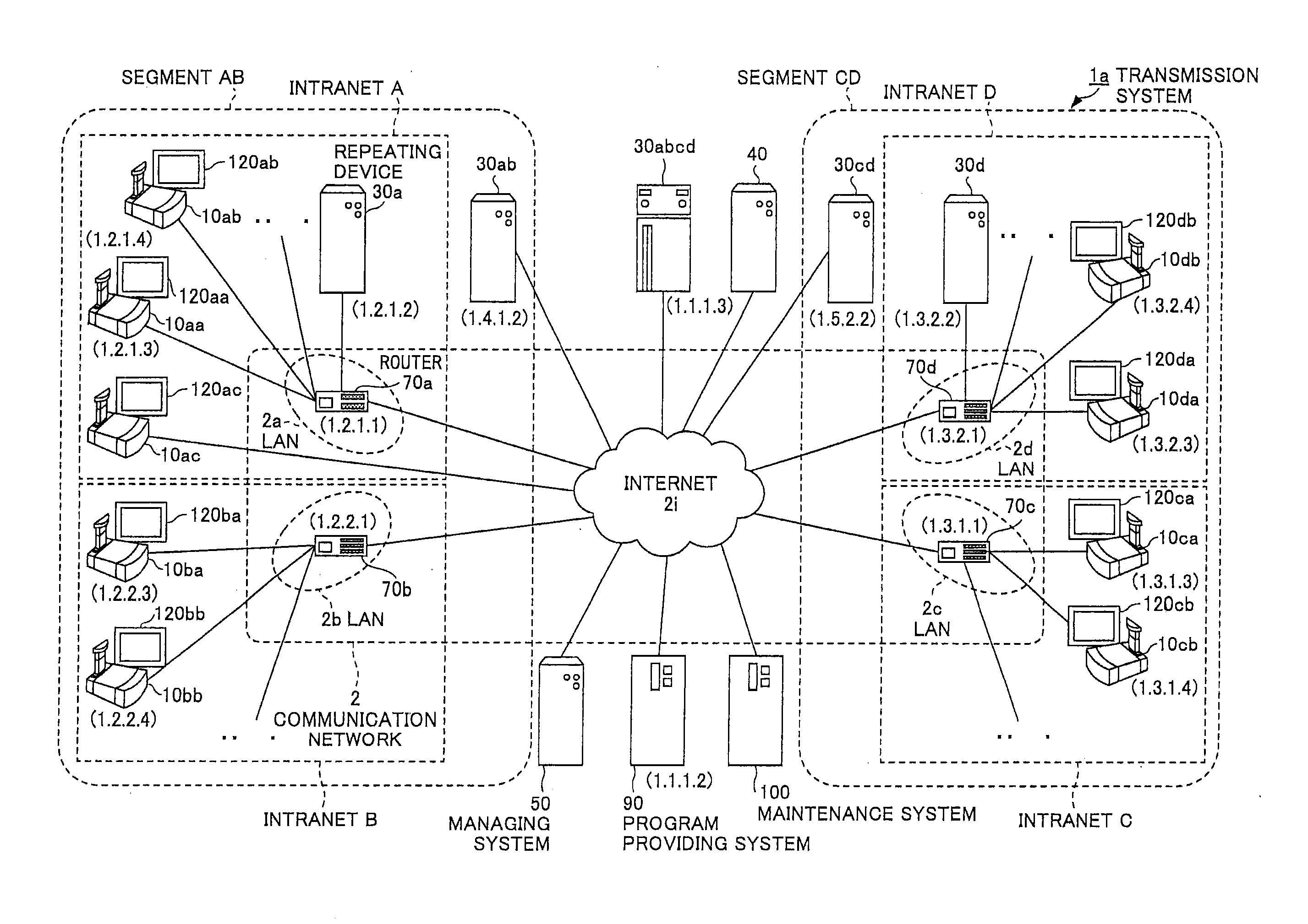
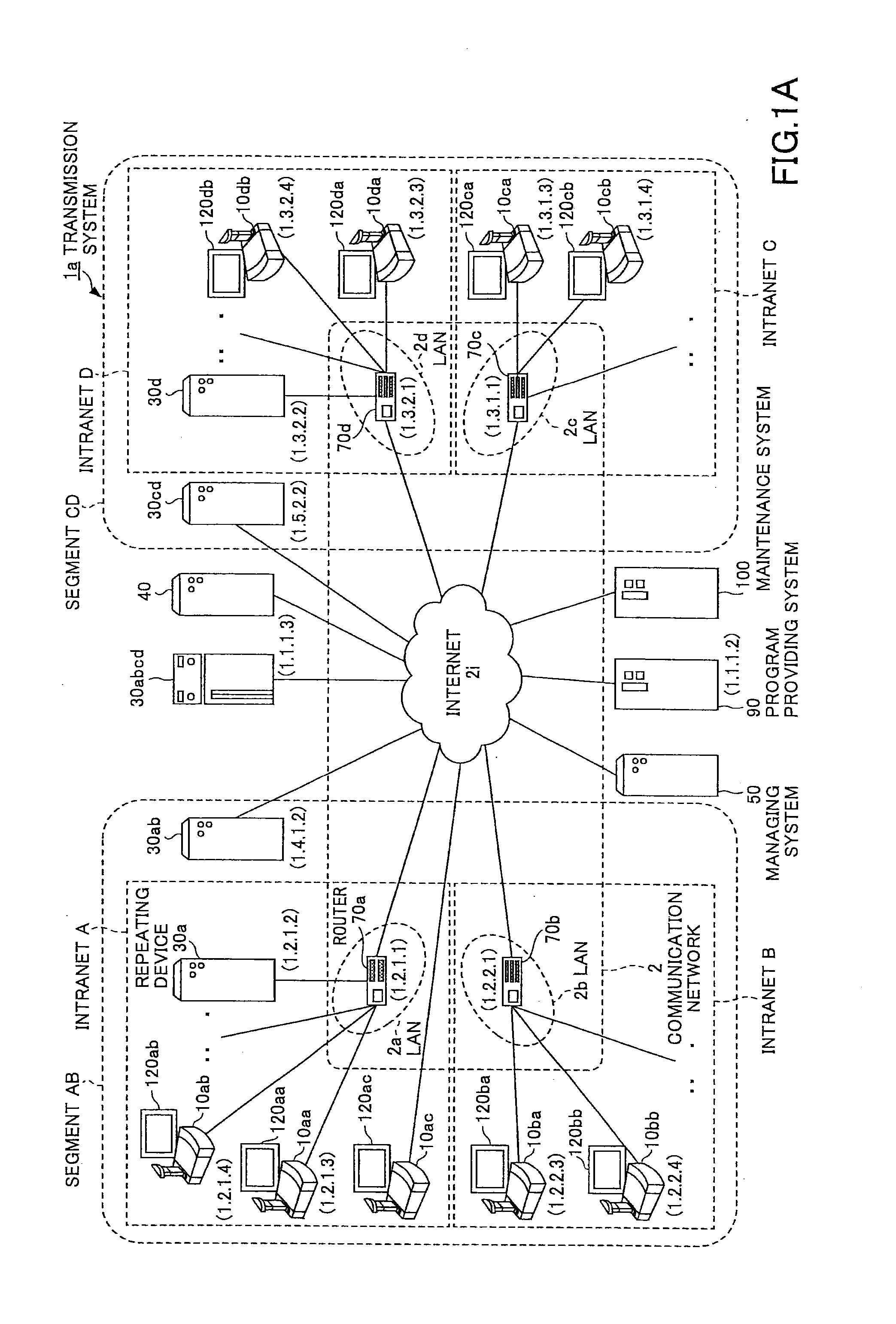
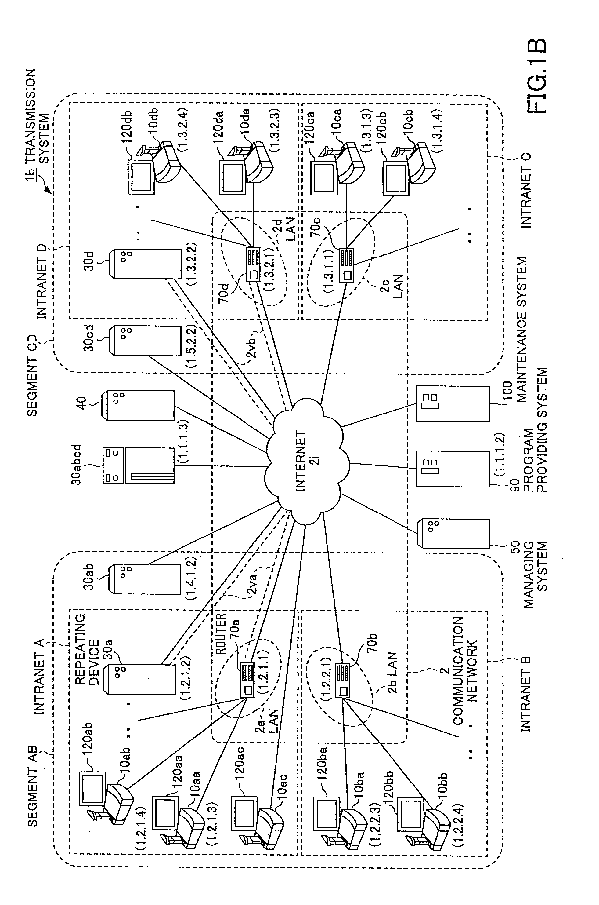
[0210]FIG. 23 is an example of an overall configuration diagram of an electronic conference system 300. The electronic conference system 300 has a video conference server 200, and two or more pairs of a terminal 10 and a PC 120. The server 200 has a management system 50, a repeating device 30, and a temporary storage for files 40. The management system 50 and the repeating device 30 have been explained already. The management system 50, the repeating device 30, and, the temporary storage for files 40 do not need to be implemented in physically separated information processing devices, but may be implemented in a single information processing device. In the present example, the information processing device is called the server 200.
[0211]As explained, the management system 50 controls communication, for example, to establish a session among terminals. The repeating device 30 relays image and audio data with selecting a route to optimally transmit the data. The temporary storage for f...
example 2
[0260]In the present example, an electronic conference system 300 will be described, in which a terminal 3 joining a conference late can share a file with terminals 1-2. Suppose a terminal 3 is a terminal that starts to participate in the conference after the conference has begun. Again in this case, it is possible to synchronize a file by having the management system 50 indicate a shared folder URI and account information to the terminal 3.
[0261]FIG. 29 is an example of a sequence chart illustrating a procedure to send / receive files among terminals in the electronic conference system 300.
[0262]S1. Conference Started
[0263]The terminals 1 and 2 have started the conference. Of course, the session has been already established.
[0264]S2. Attend Conference Late
[0265]If the power of the terminal 3 is switched on, the login requesting section 13 makes a request for a login to the management system 50. A user at a PC 3 connected to the terminal 3, specifies, for example, a target terminal am...
example 3
[0276]In the present example, a shared folder 47 after the end of a conference will be explained. If a file is stored in a shared folder 47 as described in Example 1 or 2, it is desirable to delete the file afterward for the sake of security.
[0277]FIG. 30 is an example of a sequence chart illustrating a procedure to terminate an electronic conference system 300.
[0278]S1-1, S1-2 Close Conference
[0279]A conference may be closed with events such that one of the terminals 10 indicates the end of the conference to the management system 50, all the terminals 10 in the session managing table cease responding to a query from the management system 50, etc. Suppose a conference has been closed under control of the management system 50. The management system 50 indicates the end of the conference to the terminals 1-2, respectively.
[0280]S2-1, 2-2. Unmount Shared Folder
[0281]Detecting the end of the conference, the folder mounting section 23 of the terminal 1-2 unmounts the shared folder 47 of ...
PUM
 Abstract
Description
Claims
Application Information
 - R&D
- Intellectual Property
- Life Sciences
- Materials
- Tech Scout
- Unparalleled Data Quality
- Higher Quality Content
- 60% Fewer Hallucinations
Browse by: Latest US Patents, China's latest patents, Technical Efficacy Thesaurus, Application Domain, Technology Topic, Popular Technical Reports.
© 2025 PatSnap. All rights reserved.Legal|Privacy policy|Modern Slavery Act Transparency Statement|Sitemap|About US| Contact US: help@patsnap.com


