Rotation processing machine and rotation processing method

a technology of rotating processing machine and rotating processing method, which is applied in the direction of gear teeth, gear-teeth manufacturing apparatus, work transfer apparatus, etc., can solve the problems of increasing the overall initial investment in the processing device and increasing so as to reduce the time required for changeover

Active Publication Date: 2013-08-29
AISIN AW CO LTD
View PDF3 Cites 16 Cited by
  • Summary
  • Abstract
  • Description
  • Claims
  • Application Information

AI Technical Summary

Benefits of technology

The present invention aims to provide a rotation processing machine and method that can deliver and receive a workpiece and cutting tool using the same turning loader to reduce the time required for changeover of the cutting tool. The machine is designed with a plurality of grippers that can securely hold both the workpiece and cutting tool for efficient delivery and reception. This setup reduces the overall initial investment and interfering members during changeover of the cutting tool. The technical effects of this invention include reduction of the time required for changeover of the cutting tool, improved efficiency, and cost-effectiveness.

Problems solved by technology

However, using the robot or the dedicated changeover device to perform changeover of a cutting tool that is used to process a workpiece increases overall initial investment in the processing device.
Moreover, there are many interfering members during changeover of the cutting tool, which increases the time required for changeover.

Method used


Image

  • Rotation processing machine and rotation processing method
  • Rotation processing machine and rotation processing method
  • Rotation processing machine and rotation processing method

Examples


embodiments

[0052]Embodiments of the rotation processing machine and the rotation processing method will be described below with reference to the accompanying drawings.

first embodiment

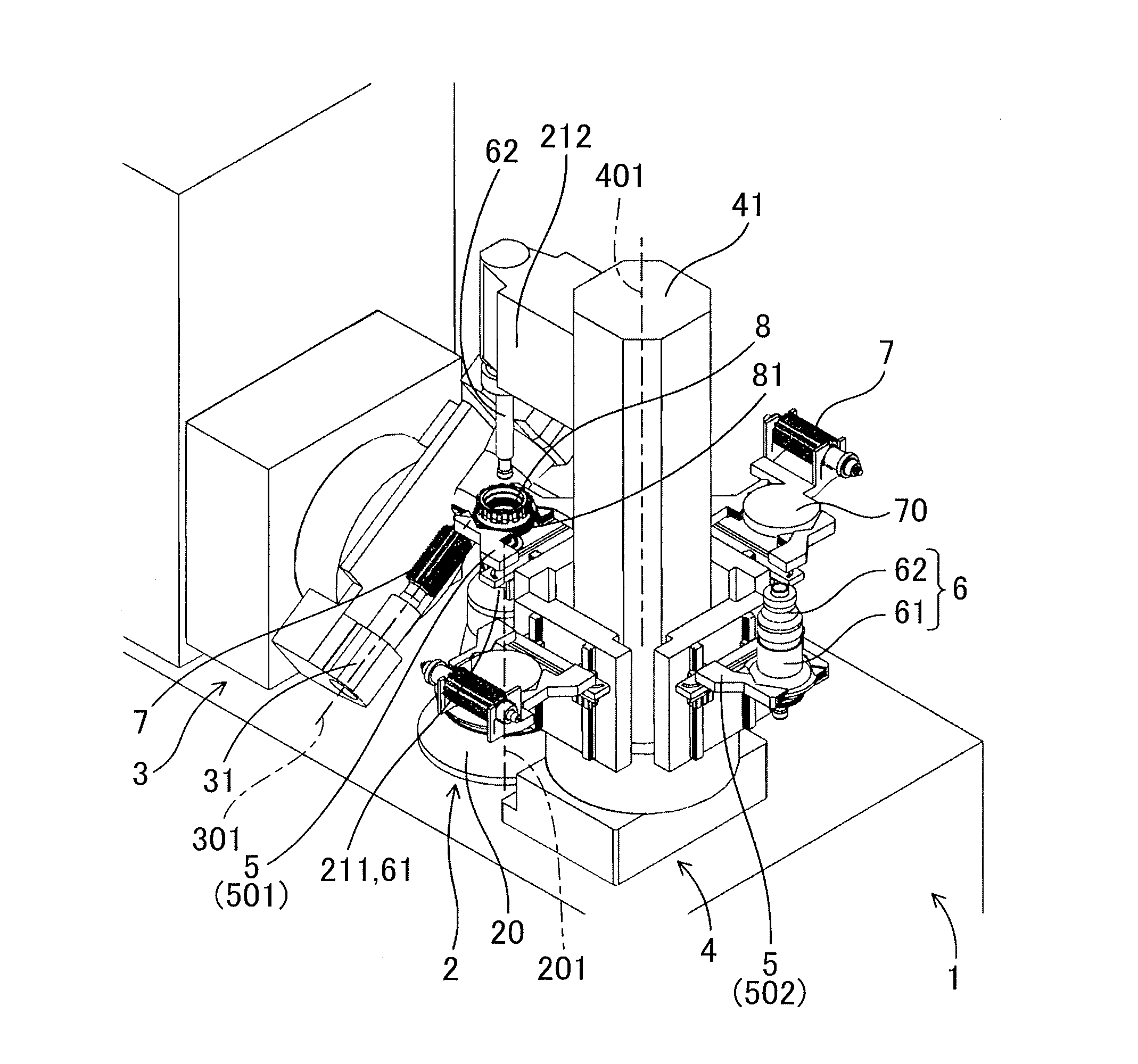
[0053]As shown in FIG. 1, a rotation processing machine 1 of the present embodiment includes a rotating device 2 that holds a workpiece 8 and rotates, a processing device 3 on which a cutting tool 7 is mounted to process the workpiece 8, and a turning loader 4 around which a plurality of grippers 5 are arranged at the same radial distance from a turning central axis 401 and which turns so that each gripper 5 sequentially faces the rotating device 2.

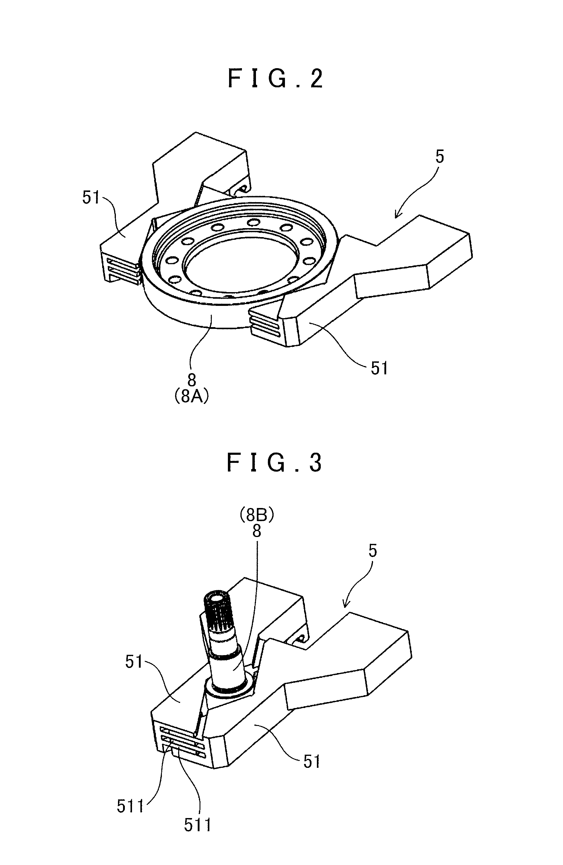
[0054]Each gripper 5 is capable of directly or indirectly holding both the workpiece 8 and the cutting tool 7, and is configured to deliver and receive the workpiece 8 to and from the rotating device 2 and to deliver and receive the cutting tool 7 to and from the processing device 3.

[0055]The rotation processing machine 1 and the rotation processing method of the present embodiment will be described in detail with reference to FIGS. 1 to 10.

[0056]As shown in FIG. 1, the processing device 3 and the rotating device 2 of the present embodime...

second embodiment

[0090]As shown in FIG. 11, a rotation processing machine 1 of the present embodiment includes a rotating device 2 that supports a cylindrical workpiece 8 via a rotation support jig 6 and rotates, a processing device 3 on which a cutting tool 7 is mounted to process the cylindrical workpiece 8, and a turning loader 4 that has a plurality of grippers 5 arranged about a turning central axis 401 and that turns so that the plurality of grippers 5 sequentially face the rotating device 2. The plurality of grippers 5 are configured to move up and down independently, and a height position of each of the plurality of grippers 5 can be set to: a first height position 50A where the gripper 5 delivers and receives the cylindrical workpiece 8 to and from the rotating device 2 as shown in FIG. 12; a second height position 50B where the gripper 5 delivers and receives the rotation support jig 6 to and from the rotating device 2 as shown in FIG. 13; and a third height position 50C where the gripper ...


PUM


Abstract

A rotation processing machine, including a rotating device that holds and rotates a workpiece; a processing device on which a cutting tool is mounted to process the workpiece; and a turning loader that has grippers arranged about a turning central axis, and that turns so that the grippers sequentially face the rotating device. The turning loader is configured to deliver and receive the workpiece to and from the rotating device by turning with the workpiece being directly or indirectly held by the gripper, and to deliver and receive the cutting tool to and from the processing device by turning with the cutting tool being directly or indirectly held by the gripper.

Description

[0001]The disclosures of Japanese Patent Application Nos. 2012-078817, 2012-038720, and 2012-161619 filed on Mar. 30, 2012, Feb. 24, 2012, and Jul. 20, 2012, respectively, including the specifications, drawings and abstracts are incorporated herein by reference in its entirety.BACKGROUND OF THE INVENTION[0002]The present invention relates to rotation processing machines and rotation processing methods capable of performing changeover of a workpiece and a cutting tool that is used to process the workpiece, by using a turning loader.DESCRIPTION OF THE RELATED ART[0003]When processing a workpiece with a cutting tool in processing devices, transfer of the workpiece and changeover of the cutting tool are performed by using separate devices. Specifically, the workpiece is set at a specific processing position by using a robot, a transfer loader, etc., and is processed by using the cutting tool. After a required number of workpieces are processed, changeover of the cutting tool is performe...

Claims


Application Information

Patent Timeline
IPC IPC(8): B23Q5/34B23Q3/157
CPCB23Q3/157B23Q5/34Y10T483/16B23Q7/10Y10T483/10B23Q1/4842Y10T483/1745Y10T483/1736Y10T409/10159Y10T409/101113Y10T409/109699Y10T409/100954Y10T409/103657B23F23/06B23F23/04B23F19/10B23F5/22B23F23/1293B23F19/102B23F5/20B23Q3/155B23Q7/04B23Q1/489B23Q7/046
Inventor KATO, SUSUMUTAKAGAI, AKIRAOTANI, MASAHIROKAWANISHI, AKITOMO
Owner AISIN AW CO LTD
Why Eureka
Try Eureka