
Light-emitting module

a technology of light-emitting modules and modules, which is applied in the direction of discharge tubes luminescnet screens, semiconductor devices for light sources, lighting and heating apparatus, etc., can solve the problems of short circuit of wiring patterns of flexible boards or electrodes of led lamps, degradation of workability, and increase in manufacturing costs, so as to achieve simple electrical connection, reduce production costs, and reduce production costs

Inactive Publication Date: 2013-08-29
TOYODA GOSEI CO LTD
View PDF2 Cites 5 Cited by
  • Summary
  • Abstract
  • Description
  • Claims
  • Application Information

AI Technical Summary

Benefits of technology

The invention reduces the problem of a shadow caused by the cover of LED lamps and improves the efficiency of light emission from LED chips. Additionally, it reduces contact resistance between the external electrode and electrode portion, facilitating better electrical connection.

Problems solved by technology

In the technique disclosed in US 2009 / 0206718 A1, when the solders are used as the conductive member, there are problems such as degradation in workability due to soldering, an increase in manufacturing cost, possibility that wiring patterns of the flexible board or electrodes of the LED lamp may be short-circuited by excessive solder, degradation in performance due to thermal stress applied during soldering, and degradation in emission quality due to a solder or a solder flux attached to the light pickup surface of the LED lamp to contaminate the light pickup surface.
In the technique disclosed in US 2009 / 0206718 A1, when the metal paste or the soft metal is used as the conductive member, there is also a problem in that the workability further degrades in comparison with the solder, thereby increasing the manufacturing cost.
In the technique disclosed in US 2009 / 0206718 A1, since the cover is disposed at a position higher than LED chips of the LED lamp, there is also a problem in that a shadow of the cover is formed on an irradiated surface irradiated with the light emitted from the LED chips, in addition to a problem in that light emitted from the LED chips may be blocked by the cover and thus emission efficiency of light from the LED chips is lowered.

Method used


Image

  • Light-emitting module
  • Light-emitting module
  • Light-emitting module

Examples


first embodiment

[0074]As shown in FIGS. 1A and 1B to FIG. 6, a light-emitting module 10 according to a first embodiment of the invention includes an LED lamp 11 (an insulating substrate 11a, a light-emitting section 11b, a sealing frame 11ca sealing body 11d, LED chips 11e, and external electrodes 11f and 11g), a flexible board 12 (electrode portions 12a to 12d, wiring patterns 12e and 12f, a mounting hole 12g, and screw holes 12h and 12i), a connection member 13 (a mounting hole 13a, screw holes 13b and 13c, convex portions 13d, and locking claws 13e), a chassis 14 (female screw holes 14a to 14d), and male screws 15.

[0075]The chassis 14 is, for example, a heat sink or a case of a light-emitting device on which the light-emitting module 10 is mounted.

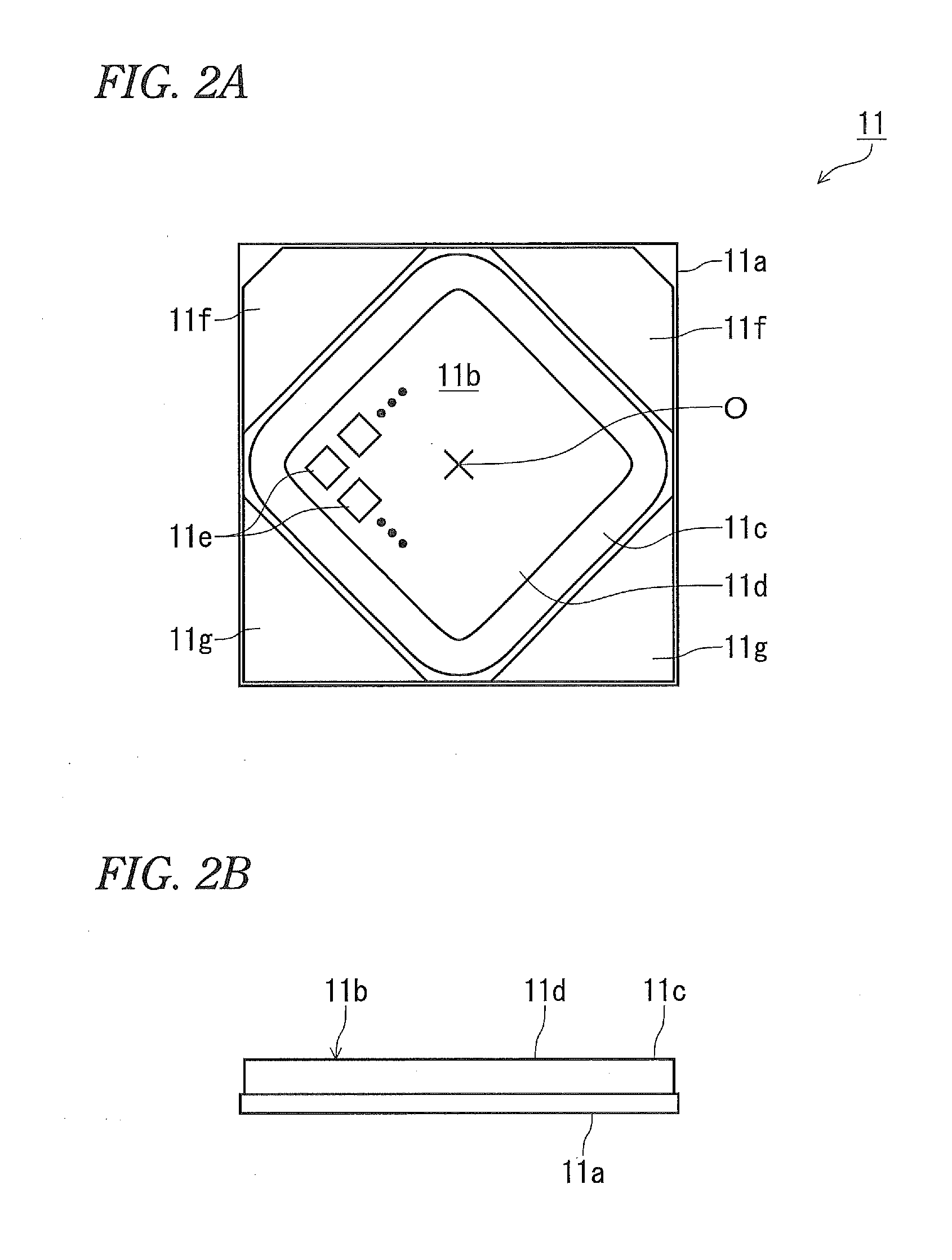
[0076]As shown in FIGS. 2A and 2B, the LED lamp (LED board) 11 includes the insulating substrate 11a, the light-emitting section 11b, the sealing frame 11c, the sealing body 11d, the LED chips 11e, and the external electrodes 11f and 11g.

[0077]The ins...

second embodiment

[0142]As shown in FIGS. 7A and 7B to FIG. 10, a light-emitting module 20 according to a second embodiment of the invention includes an LED lamp 21 (a sealing body 11d, LED chips 11e, an insulating substrate 21a, a light-emitting section 21b, a sealing frame 21c, notched portions 21d and 21e, external electrodes 21f and 21g, a screw hole 21h, and mounting concave portions 21i to 21l), flexible boards 22a and 22b (electrode portions 22c and 22d, wiring patterns 22e, and mounting concave portions 22f and 22g), a connection member 23 (screw holes 23c, convex portions 23d, and locking claws 23e and 23f), a chassis 14, and male screws 15.

[0143]As shown in FIGS. 8A and 8B, the LED lamp (LED board) 21 includes the sealing body 11d, the LED chips 11e, the insulating substrate 21a, the light-emitting section 21b, the sealing frame 21c, the external electrodes 21f and 21g, the screw hole 21h, and the mounting concave portions 21i to 21l.

[0144]The insulating substrate 21a has a square plate sh...

third embodiment

[0199]As shown in FIGS. 11A, 11B, and 11C to FIGS. 16A and 16B, a light-emitting module 30 according to a third embodiment of the invention includes an LED lamp 11 (an insulating substrate 11a, a light-emitting section 11b, a sealing frame 11c, a sealing body 11d, LED chips 11e, and external electrodes 11f and 11ga flexible board 31 (electrode portions 31a to 31d, wiring patterns 31e to 31j, a mounting hole 31k, bending portions 31l to 31o, and a top portion 31p), a connection member 32 (a mounting hole 32a, screw holes 32b and 32c, convex portions 32d, locking claws 32e, a housing section 32f, and mounting portions 32g and 32h), and a heat dissipater 33 (notched portions 33aand is mounted on and fixed to a chassis 14 using male screws 15.

[0200]As shown in FIGS. 12A and 12B and FIGS. 13A, 13B, and 13C, the flexible substrate 31 includes the electrode portions (connection portions) 31a to 31d, the wiring patterns 31e to 31j, the mounting hole 31k, the bending portions 31l to 31o, and...


PUM


Abstract

A light-emitting module includes: an LED lamp comprising; a flexible board; and a connection member that sandwiches and fixes the LED lamp and the flexible board. An electrode portion of the flexible board is pressed against an external electrode of the LED lamp by the connection member, whereby the external electrode directly contacts and is electrically connected to the electrode portion. A portion of the connection member highest from the substrate is lower than a portion of the sealing body highest from the substrate.

Description

BACKGROUND[0001]1. Technical Field[0002]The present invention relates to a light-emitting module.[0003]2. Background Art[0004]US 2009 / 0206718 A1 discloses an LED lamp module which includes a flexible board disposed on a metal base, a surface-mounted LED lamp disposed on the flexible board, and a cover covering the flexible board and the LED lamp, in which the bottom surface of the LED lamp and the flexible board are electrically connected to each other via a conductive member and a light pickup surface is disposed on the surface of the LED lamp, and in which the cover covers a part of the LED lamp other than the light pickup surface and presses the LED lamp.[0005]US 2009 / 0206718 A1 also discloses that the flexible board is pressed by a protrusion formed on the cover.[0006]US 2009 / 0206718 A1 also discloses that examples of the conductive member include a metal paste in which metal such as Ag is contained in a resin, soft metal such as Au, and solders such as AuSn, AuGe, and AuSi and ...

Claims


Application Information

Patent Timeline
Patent Type & Authority Applications(United States)
IPC IPC(8): H05B33/06
CPCH05B33/06H01L33/486F21Y2101/02F21K9/00F21V19/003H01L33/62F21Y2115/10
Inventor KATO, HIDEAKI
Owner TOYODA GOSEI CO LTD
Learn More