
Switch Assembly With Sequentially Actuated Power and Neutral Switching

a technology of power and neutral switching and switch assembly, which is applied in the direction of switches with two operating positions, contact, electrical equipment, etc., can solve the problems of complex switching sequence, complex power source switching operation, and many prior art devices that fail to address such events

Active Publication Date: 2013-08-29
RELIANCE CONTROLS
View PDF12 Cites 23 Cited by
  • Summary
  • Abstract
  • Description
  • Claims
  • Application Information

AI Technical Summary

Benefits of technology

The present invention provides a switch assembly that ensures electrical isolation of utility and generator power during a transfer of input power from one source to another. The switch assembly includes a single actuator that controls the sequence of operation of neutral and power connections to circuits associated with the utility and generator power supplies. The switch assembly also includes a positive switch contact arrangement and a neutral switch contact arrangement with geometrically different constructions so as to avoid an open neutral condition. The technical effect of the invention is to improve safety and reliability when switching between power sources.

Problems solved by technology

Proper sequencing of the various conducting states of the neutral and power or “hot” leads associated with the respective loads and alternate power sources is a significant issue when switching both the power (hot) and neutral conductors in power transfer equipment.
Unfortunately, many prior art devices fail to address such occurrences or require complex switching sequences that could be inadvertently incorrectly performed by users during power source switching activities without proper switch interlock constructions.
Unfortunately, providing various switch interlock arrangements tends to complicate the power source switching operation and can increase the cost associated with forming a desired interlocking arrangement.

Method used


Image

  • Switch Assembly With Sequentially Actuated Power and Neutral Switching
  • Switch Assembly With Sequentially Actuated Power and Neutral Switching
  • Switch Assembly With Sequentially Actuated Power and Neutral Switching

Examples


Embodiment Construction

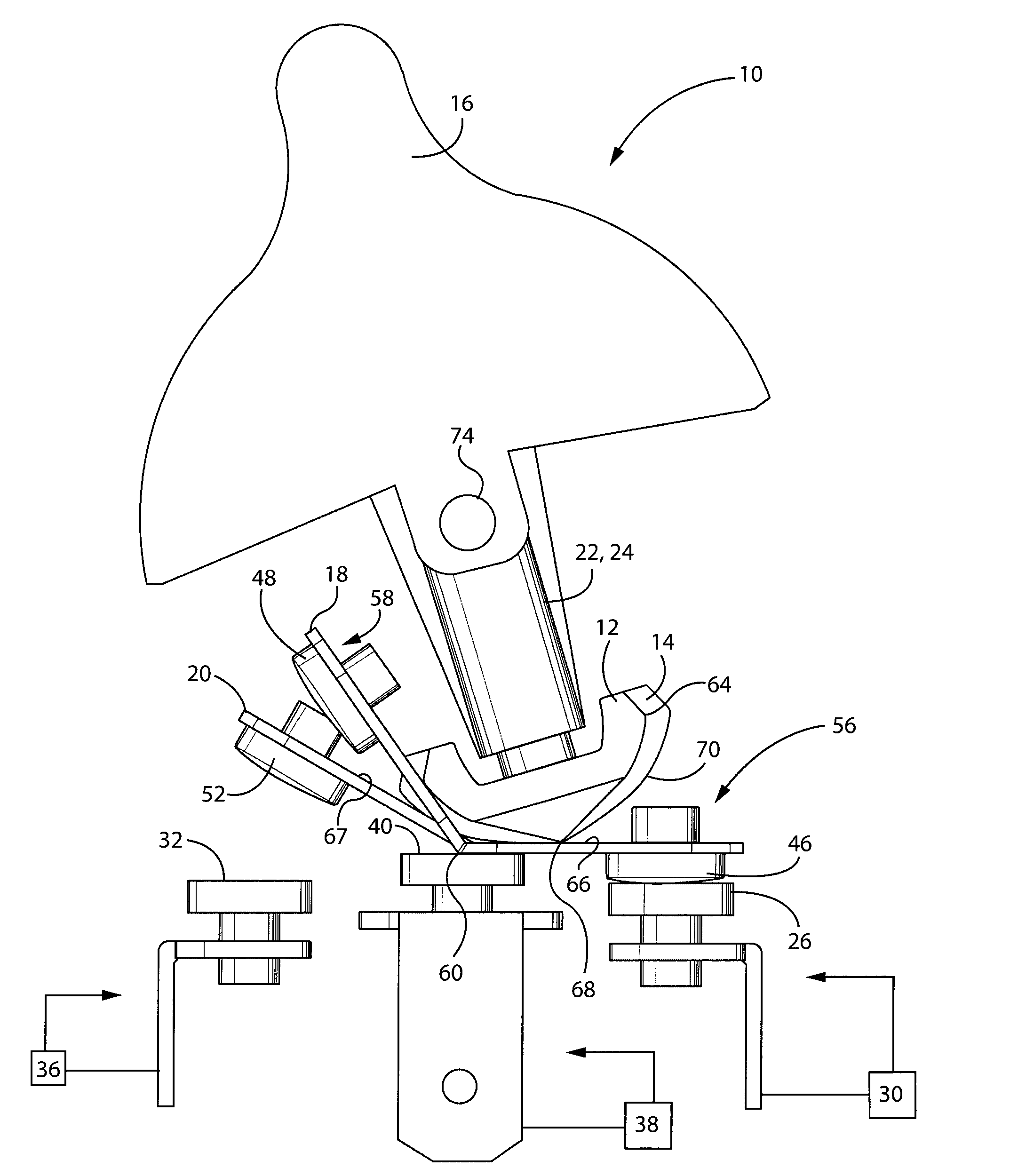
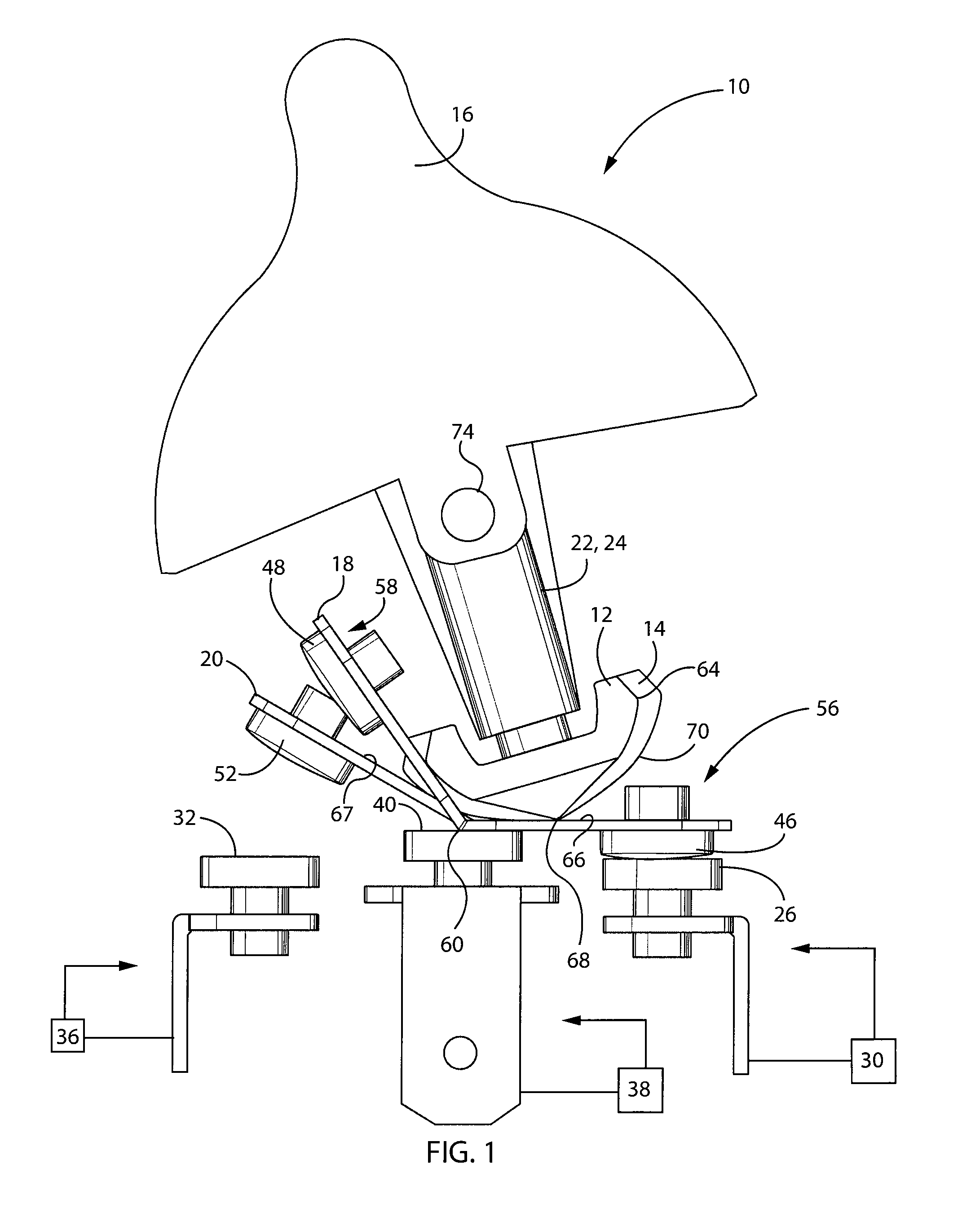
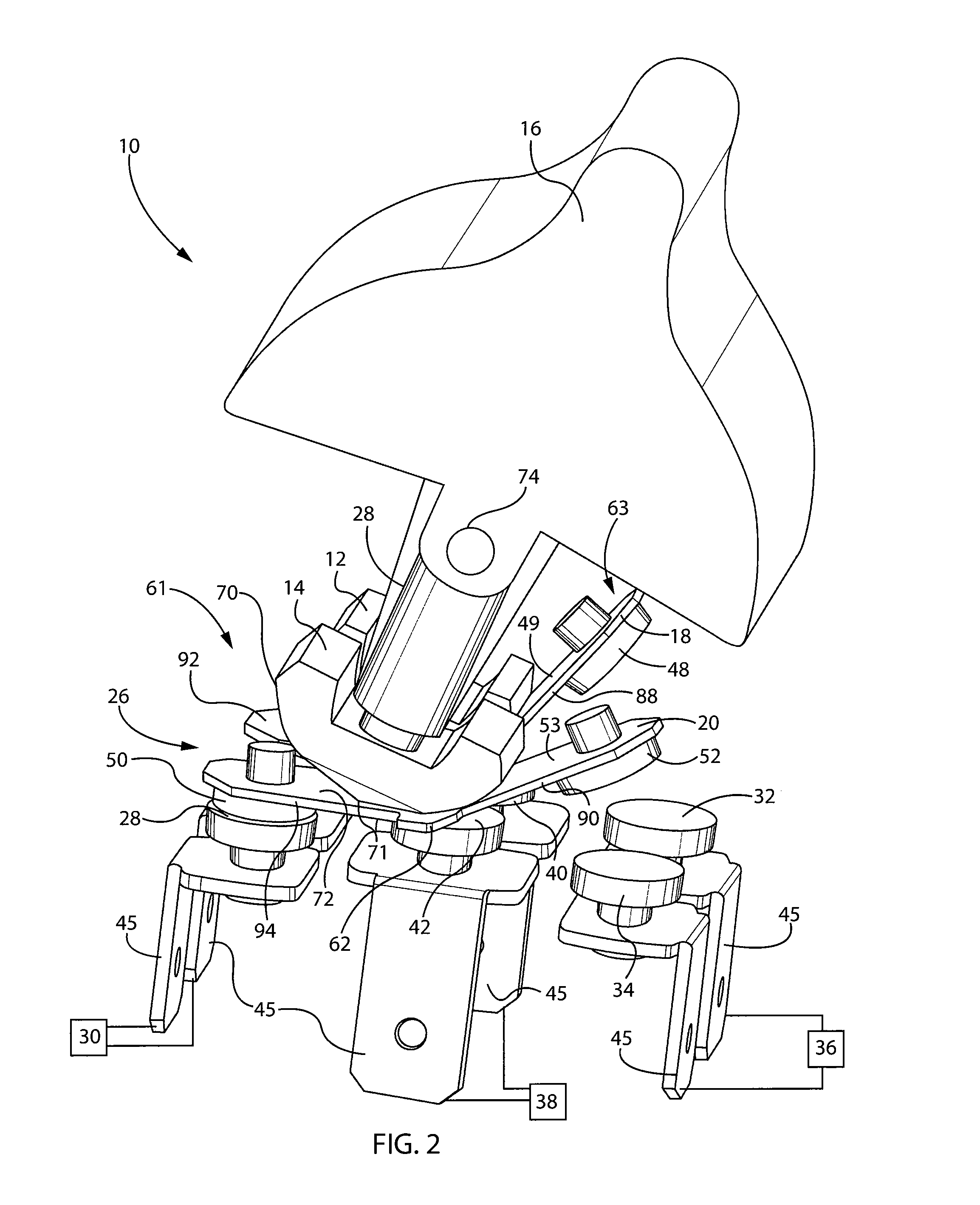
[0021]FIGS. 1-7 show a rocker-type switch or switch assembly 10 according to a representative embodiment of the present invention. Referring to FIGS. 1 and 2, switch assembly 10 includes a first control member or first movable element 12 and a second control member or second movable element 14 that are operably coupled to one another via a movable actuator 16 of the switch assembly 10. The switch assembly 10 may be in the form of a single-pole, double-throw switch assembly or any other such type of switch generally known in the art. As will be discussed in further detail, the first and second movable elements 12 and 14 are constructed so as to be geometrically different from one another but connected so as to be movable together.

[0022]As explained further below, the geometrical differences between movable elements 12, 14 result in the ability of one of the movable elements to make an electrical connection with a respective portion of a circuit associated with the respective movable ...


PUM

PropertyMeasurementUnit
angleaaaaaaaaaa
angleaaaaaaaaaa
obtuse angleaaaaaaaaaa

Abstract

A switch assembly and method of switching a load between a first power source and a second power source that maintains a desired sequencing of the making and breaking of both the neutral and power connections in response to a single user input. The switch assembly includes an actuator that is movable between a first position and a second position and a first movable element and a second movable element that are operably coupled to one another and the actuator. A positive switch contact arrangement is coupled with the first movable element and a neutral switch contact arrangement is coupled with the second movable element. The positive switch contact arrangement and the neutral switch contact arrangement comprise geometrically different constructions so that moving the actuator between the first position and the second position avoids an open neutral condition.

Description

CROSS-REFERENCE TO RELATED APPLICATIONS[0001]This application claims priority to U.S. Provisional Patent Application Ser. No. 61 / 604,842, filed on Feb. 29, 2012, titled “Sequentially Actuated Power And Neutral Switch” and the entire contents of which are expressly incorporated herein.BACKGROUND AND SUMMARY OF THE INVENTION[0002]The present invention relates to a switch assembly for switching between power sources, such as between utility power and an auxiliary power source such as, for example, a backup power source such as a gasoline or other combustible fuel powered generator. The switch is configured to prevent the occurrence of open-neutral configurations that present the potential for high-voltages, e.g., 240 VAC, to be erroneously applied to 120 VAC equipment or appliances, which may cause damage to the equipment or appliances.[0003]Electrical panels, breaker boxes, or load centers frequently include a main contactor, switch, or breaker, which electrically isolates a series of...

Claims


Application Information

Patent Timeline
Patent Type & Authority Applications(United States)
IPC IPC(8): H01H9/24H01H11/00
CPCH01H23/168H01H2300/018H01H9/24Y10T29/49105H01H23/205H01H23/24H01H1/2016H01H11/00
Inventor CZARNECKI, NEIL A.
Owner RELIANCE CONTROLS
Learn More