
Elevator

a technology of elevators and frames, applied in the field of elevators, can solve the problems of forming standing platforms, risk of falling, cramped spaces between them, etc., and achieve the effect of simple arrangement, and rigidity effect of frames

Active Publication Date: 2013-08-29
KONE CORP
View PDF17 Cites 9 Cited by
  • Summary
  • Abstract
  • Description
  • Claims
  • Application Information

AI Technical Summary

Benefits of technology

The invention is a new elevator car design that uses a thinner roof structure and a hoisting system to suspend the car. This design reduces the amount of load bearing on the roof beams and allows for a smaller roof structure. Additionally, the design also prevents the need for ridges on the sides of the trough which may attract goods or people. These features make the elevator car safer, more efficient, and more user-friendly.

Problems solved by technology

A problem of solutions according to prior art is, inter alia, that the high and wide ridge-shaped overall structure of the upper horizontal beam system with the components connected to it has resulted in the forming of standing platforms to the sides of the structure in question.
The platforms on the sides are at a distance from each other and between them is a horizontal beam system causing a risk of stumbling.
In these types of solutions the beam systems are near each other, the spaces between them are cramped and the elevator components effectively fill them.
In these types of solutions the working platforms are formed on the outer sides of a high and wide upper horizontal beam system, and crossing over, crossing under or otherwise steeping onto the point of the upper horizontal beam system is a safety risk.
The space needed by a workman does not in this case extend to high above the car, and working in the center area of the car is possible, but one problem is the complex structure because the roof needs to be opened for enabling servicing.

Method used


Image

  • Elevator
  • Elevator
  • Elevator

Examples


Embodiment Construction

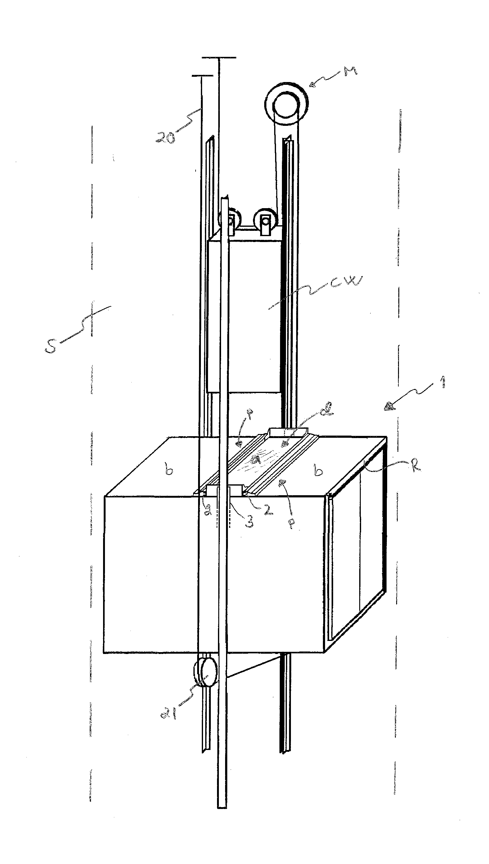
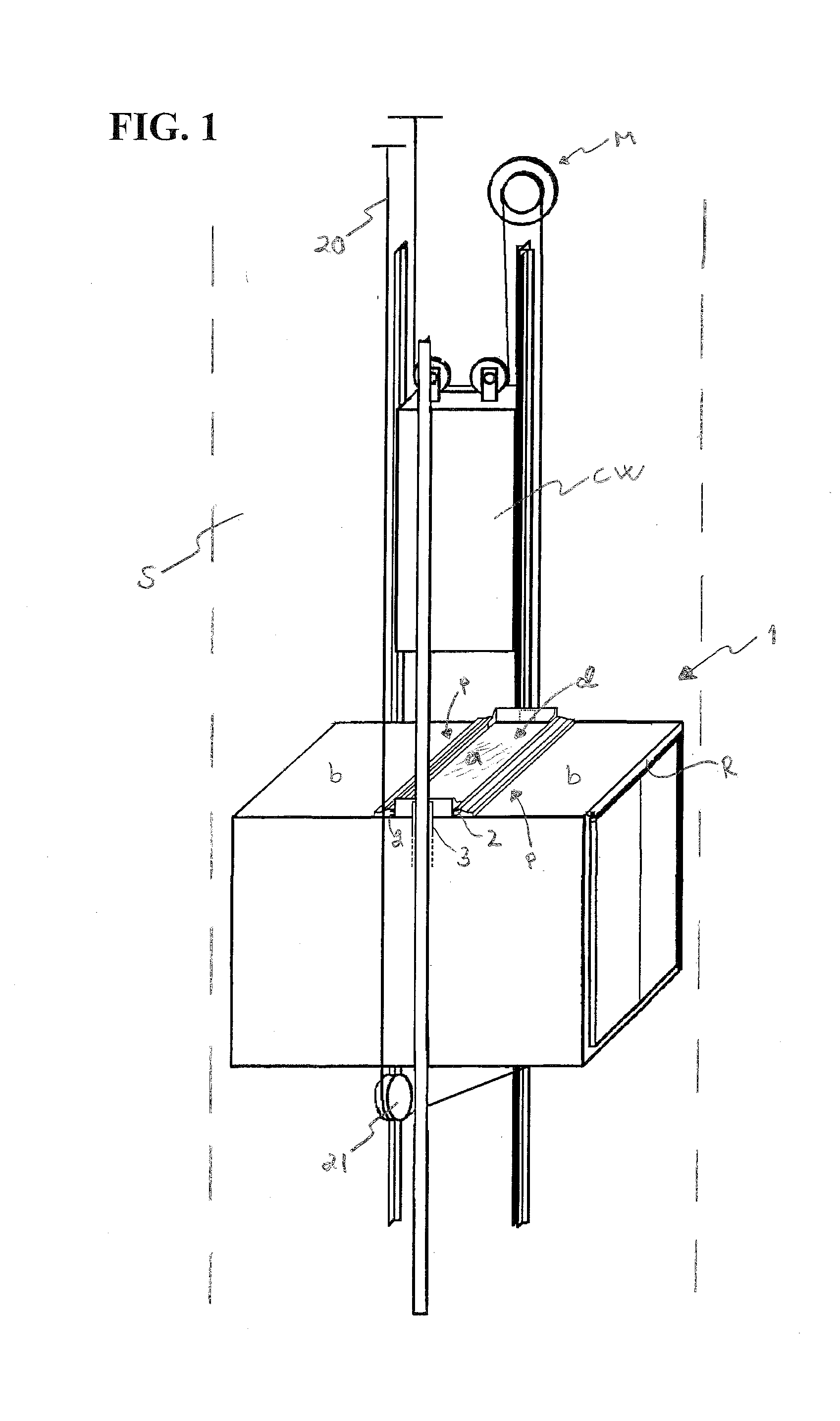
[0079]FIG. 1 presents an elevator according to the invention, which elevator comprises an elevator hoistway S, and an elevator car 1 arranged to move in the elevator hoistway, which elevator car 1 comprises an interior I, which is bounded by the walls, roof, floor and door of the elevator car. The elevator car is moved with a hoisting machine M via hoisting ropes 20.

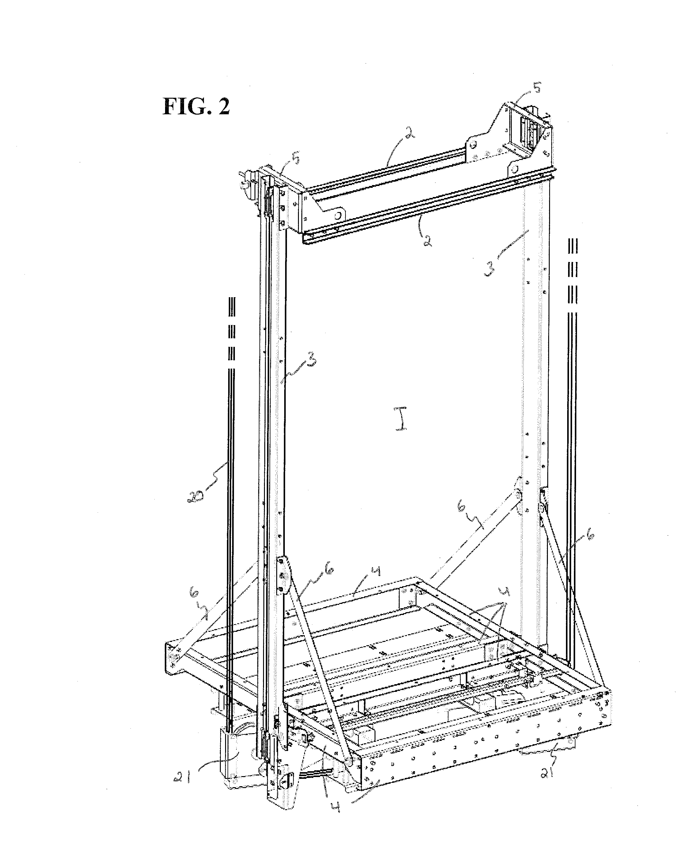
[0080]The elevator car 1 comprises a frame structure, which comprises two parallel, horizontal, elongated roof beams 2 in connection with the roof R of the elevator car 1, said beams being integrated as a part of the structure of the roof and at a horizontal distance from each other, between which roof beams 2 is an upward-opening elongated trough d, which comprises an upward-facing base surface and side surfaces. The trough d is the space between the beams, which space has a base surface, which is essentially (preferably at least 30 mm, more preferably more) lower than the top surfaces j of the roof beams 2. For enablin...


PUM


Abstract

An elevator includes an elevator hoistway with an elevator car arranged to move therein. The elevator car includes an interior bounded by at least the elevator care roof. A frame structure includes two parallel, horizontal, elongated roof beams that are at a horizontal distance from each other. Between the roof beams is a trough that has an upward-facing base surface, and a standing platform in connection with the roof of the elevator car that includes a standing surface, immediately above which is a space free of the parts of the elevator car and free of the ropes of the elevator, for enabling standing on top of the standing surface at least when the elevator car is situated at a distance from the top end of the elevator hoistway. The standing surface forms at least a part of the base surface of the trough.

Description

FIELD OF THE INVENTION[0001]The object of the invention is an elevator, more particularly an elevator applicable to the transporting of people and / or of freight.BACKGROUND OF THE INVENTION[0002]Elevator cars are conventionally formed to comprise a load-bearing frame structure, i.e. a car sling, which comprises a lower horizontal beam system and an upper horizontal beam system, as well as a vertical beam system of a first side and a vertical beam system of a second side, which beam systems are connected to each other so that they form a closed loop, inside which loop is an interior comprised in a car box fixed to the beam systems, which interior can receive goods and / or passengers for conveying them in the interior of the elevator car. Conventionally the car box has been essentially fully inside the aforementioned loop. Also known in the art are elevator cars, in which the vertical beams forming the aforementioned loop are integrated as a part of the walls / roof of the car box. A prob...

Claims


Application Information

Patent Timeline
IPC IPC(8): B66B11/02
CPCB66B11/0206B66B11/0226B66B11/0246B66B11/024B66B11/0233B66B11/0253
Inventor MIELONEN, JUHARASANEN, MATTINATARAJAN, NITHIL KARIMPANACKALBJORNI, OSMOBELLO, PAULAALBU, RAZVANMANNER, TIMOSOMMA, TUULI
Owner KONE CORP
Learn More