
Medical Injection Device

a technology of injection device and injection needle, which is applied in the direction of intravenous device, other medical devices, infusion needles, etc., can solve the problems of decreased spring tension, decreased force, and inconvenience for users, and achieves the effect of more quiet performan

Active Publication Date: 2013-08-15
NOVO NORDISK AS
View PDF17 Cites 80 Cited by
  • Summary
  • Abstract
  • Description
  • Claims
  • Application Information

AI Technical Summary

Benefits of technology

This patent describes a device that helps users insert needles into injection sites with manual force. The device is designed to transfer the force from the user's hands to the needle, making the insertion process easier and more controllable. The needle can be hidden from the user's sight during the injection, which reduces any potential uneasiness. The device has two parts of movement: an initial movement that inserts the needle and an activation that activates the injection mechanism. The device may also have a deflection element that helps drive the piston and a gradual release of accumulated energy to assist in the needle insertion process. Overall, the device improves the user's ability to control the needle insertion and makes the injection process less intimidating.

Problems solved by technology

While the above devices aim at providing a high level of automation, injection devices that provide automatic insertion of the needle into the dermis also prevent the user from controlling the insertion, which can lead to uneasiness for the user.
One problem associated with auto-injectors is that the piston is moved forward, the tension of the spring decreases which in turn decreases the force of the spring pressing on the piston.
However, these solutions are somewhat problematic in that the energy used to provide the audible feedback is required near the end of the injection where the spring force available for driving the injection is at a minimum.
However, devices wherein parts remain in a tensioned state during storage generally leads to creep of the material which generally results in a non-optimal performance.
Still other problems are associated with auto-injectors that use a medicament cartridge and a needle assembly that during storage is kept in a separated configuration.
Because of the high speed of movement this stop will emit a considerable amount of noise which can be heard by the user.
This sound can cause uneasiness with the user, thus resulting in decreased confidence toward the product.

Method used


Image

  • Medical Injection Device
  • Medical Injection Device
  • Medical Injection Device

Examples


first embodiment

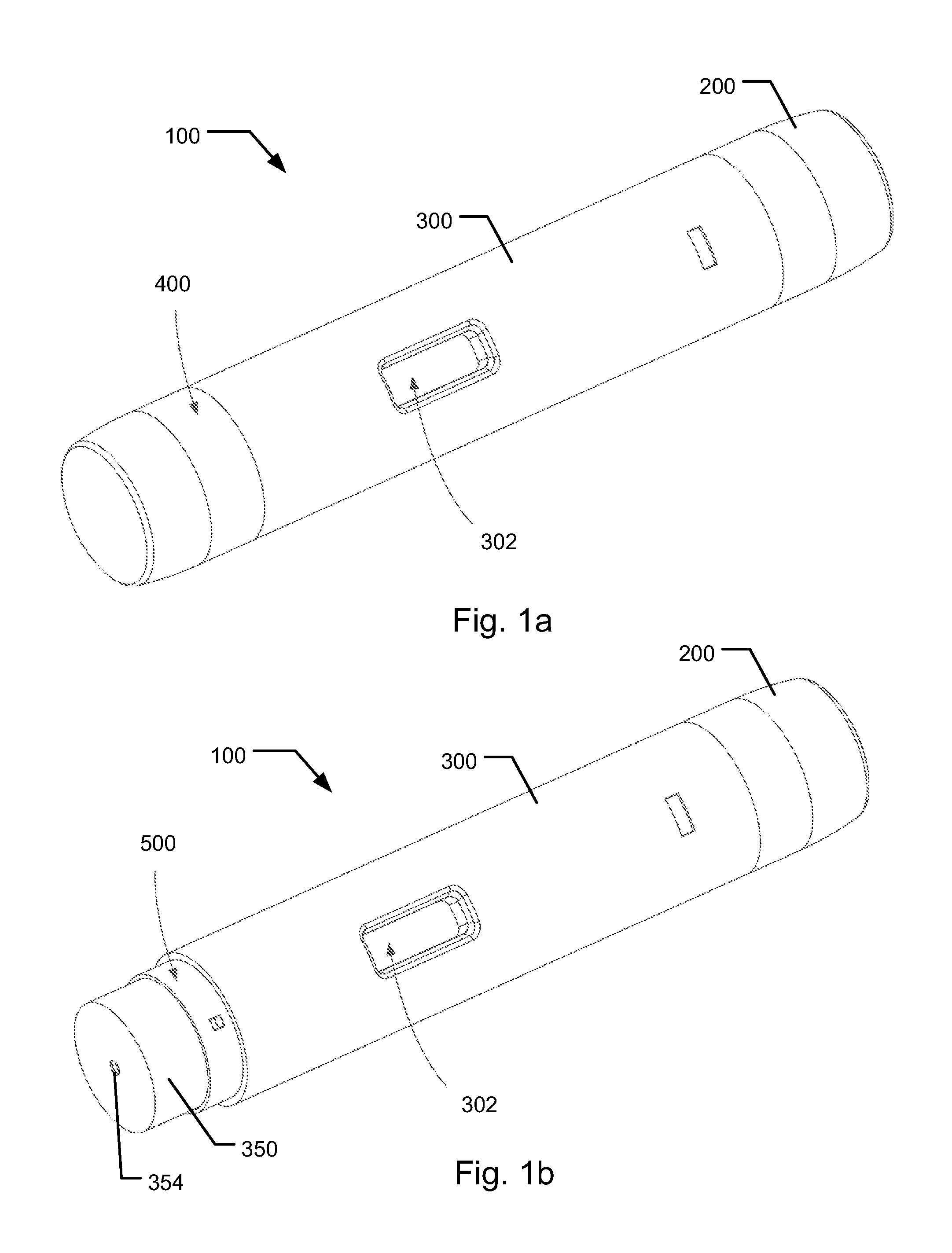
[0055]FIGS. 1a and 1b are external perspective views of an injection device according to the invention,

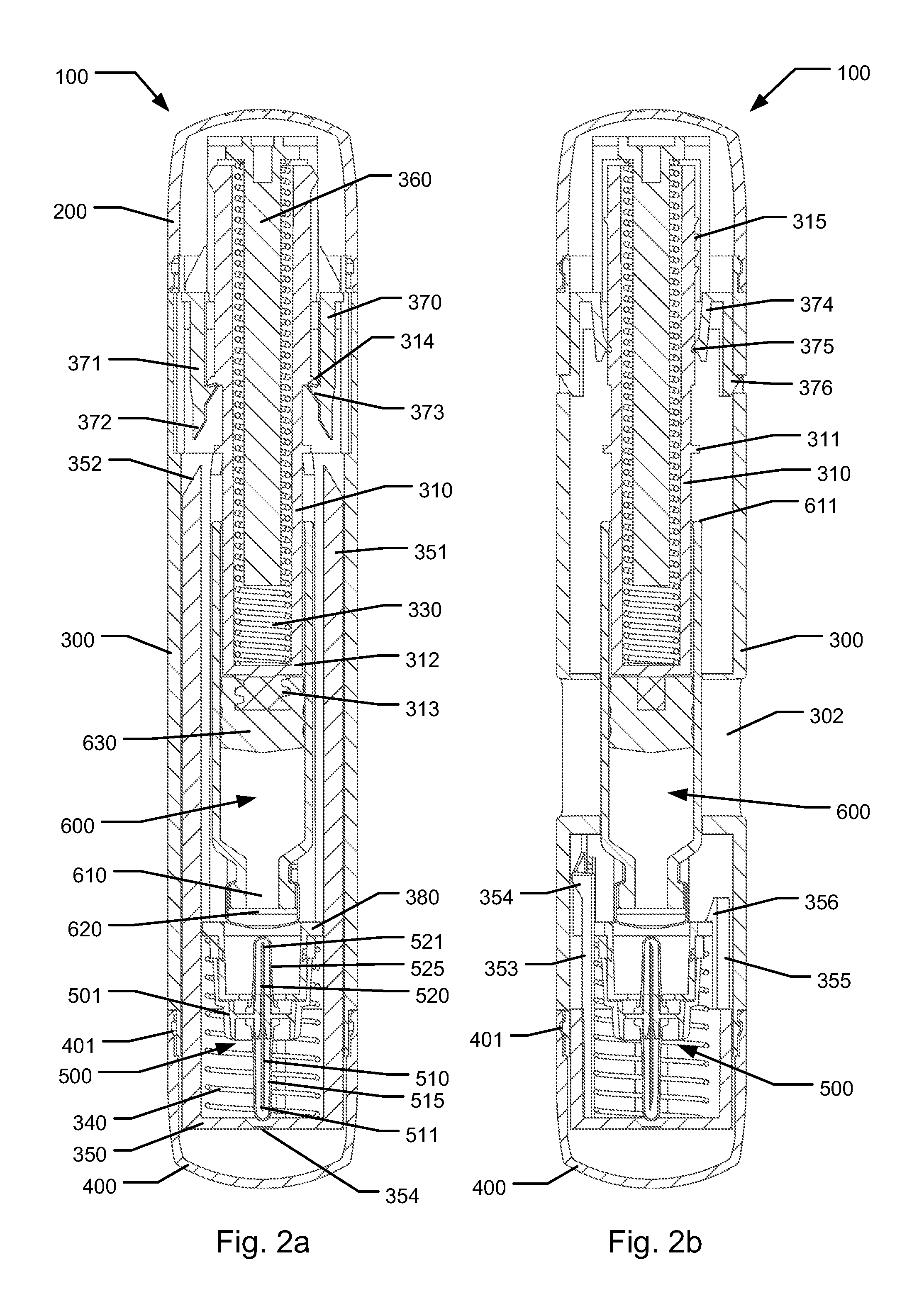
[0056]FIGS. 2a and 2b shows front sectional views and side sectional views of the first embodiment illustrating a storage condition,

[0057]FIGS. 3a and 3b shows front sectional views and side sectional views of the first embodiment illustrating a state where the front needle fully protrudes from the needle shield,

[0058]FIGS. 4a and 4b shows front sectional views and side sectional views of the first embodiment illustrating a state where the cartridge connects to the needle for initial fluid delivery,

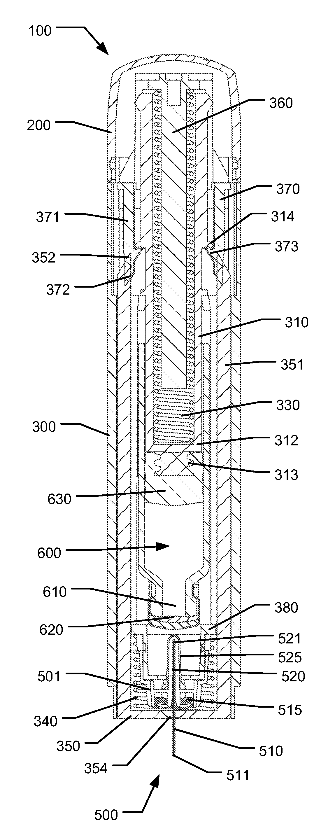
[0059]FIG. 4c is a detailed view of the device illustrated in FIG. 4a showing elements of the retainer in its released state,

[0060]FIGS. 5a and 5b shows front sectional views and side sectional views of the first embodiment illustrating a state at the end of dose condition,

[0061]FIGS. 6a and 6b shows front sectional views and side sectional views of the first embodiment illustrating a sh...

second embodiment

[0065]FIGS. 10a, 10b, 10c and 10d respectively show sectional views of an injection device according to the invention in an initial storage state, a needle protruding state, a state where the cartridge connects to the needle for initial fluid delivery and an end of dose state,

third embodiment

[0066]FIGS. 11a-11c shows detailed sectional views of an end of dose confirmation indicator in different states


PUM


Abstract

The present invention relates to medicament injection devices (100). A cartridge (600) with a septum and a needle unit (500) having front and rear needles (510, 520) are configured for relative movement from a state where the septum is sealed to a state where the septum is pierced by the rear needle (520). The injection device (100) may include a needle shield (350) and be configured for piercing the septum by the rear needle (520) when the front needle (510) is operated relative to the needle shield (350). The injection device (100) may also include a damping mechanism configured for limiting the speed of movement of the cartridge relative to the needle unit. The injection device (100) may also include an indicator generating a signal when a piston driver has travelled the complete stroke length, wherein the indicator has a deflection element that is deflected prior to or during movement of the cartridge relative to the housing.

Description

FIELD OF THE INVENTION[0001]The present invention relates to injection devices for injecting a medicament. In particular the present invention relates to injection devices for injecting a medicament from a held cartridge and improvements relating to the performance of such injection devices.BACKGROUND OF THE INVENTION[0002]In relation to some diseases patients must inject a medicament on a regular basis such as once weekly, once daily or even a plurality of times each day. In order to help patients overcome fear of needles, fully automatic injection devices have been developed that makes the use of an injection device as simple as possible. Such devices are typically designed such that a user shall position the injection device onto the injection site and activate the device. Such activation causes the device to insert a needle into the skin, eject a dose of the medicament and subsequently move the needle into a shielded position.[0003]Generally, for injection devices of the above t...

Claims


Application Information

Patent Timeline
IPC IPC(8): A61M5/32A61M5/50
CPCA61M5/2033A61M5/326A61M5/482A61M5/484A61M2005/2013A61M5/5086A61M2005/3267A61M2205/581A61M2205/582A61M5/3287A61M5/3297A61M2005/3247
Inventor PEDERSEN, SIMON MUNCHRADMER, BOWINDUM, JESPER PETERJENSEN, SOEREN DYRINGPLAMBECH, CHRISTIANNIELSEN, CHRISTIAN HOEJRIS
Owner NOVO NORDISK AS
Learn More