Electrophoretic displays
a technology of electro-osmosis and display screen, applied in the field of electro-osmosis display, can solve the problems that the electro-osmosis can easily reach the speed of osmosis, and achieve the effect of high field, strong electro-osmotic flow and high for
- Summary
- Abstract
- Description
- Claims
- Application Information
AI Technical Summary
Benefits of technology
Problems solved by technology
Method used
Image
Examples
Embodiment Construction
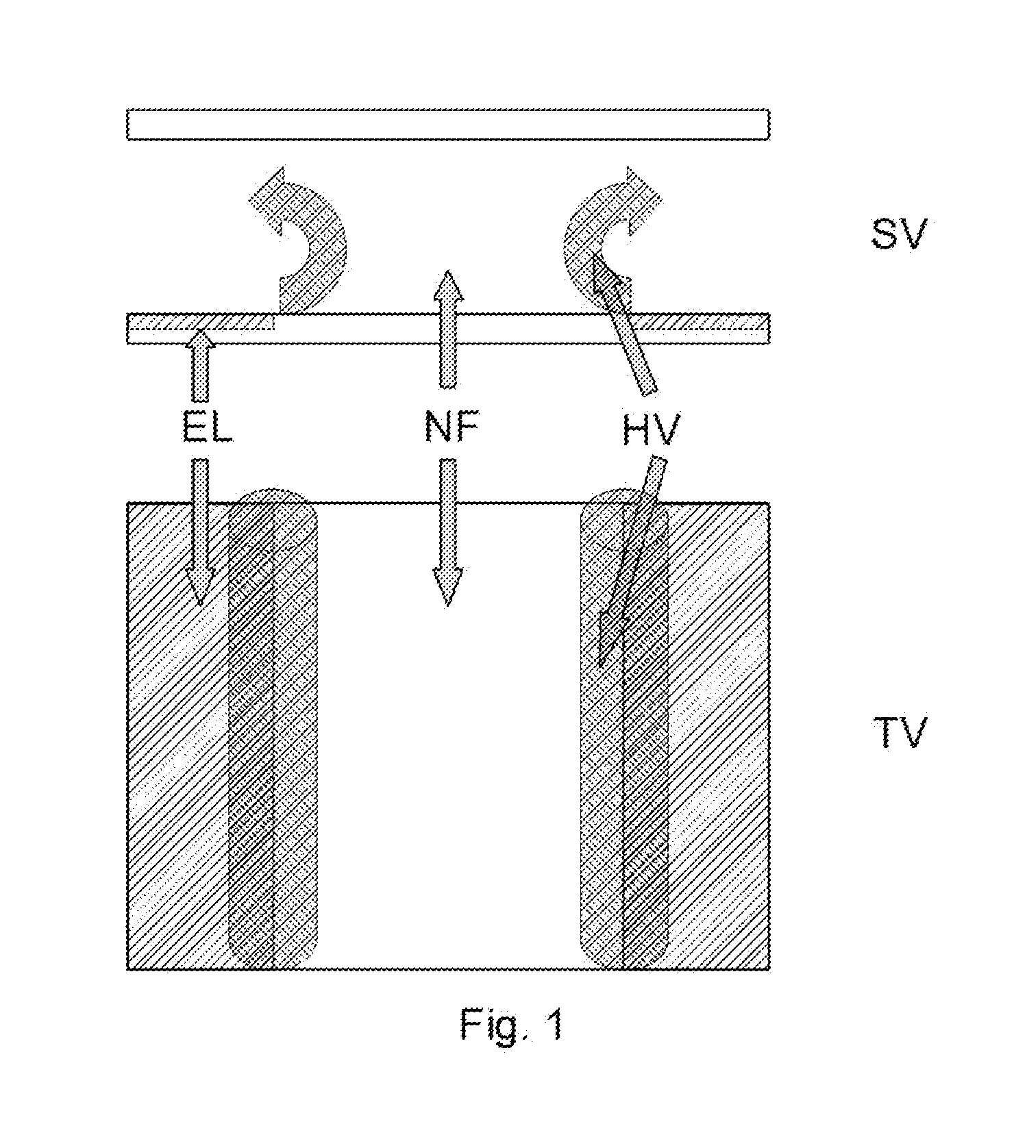
[0016]FIG. 1 shows a side view SV and a top view TV of a pixel in which the liquid flow is limited to the outer edges. The electrode is referred to as E1. HV indicates a horizontal vortex and the reference NF means “no flow” of liquid.
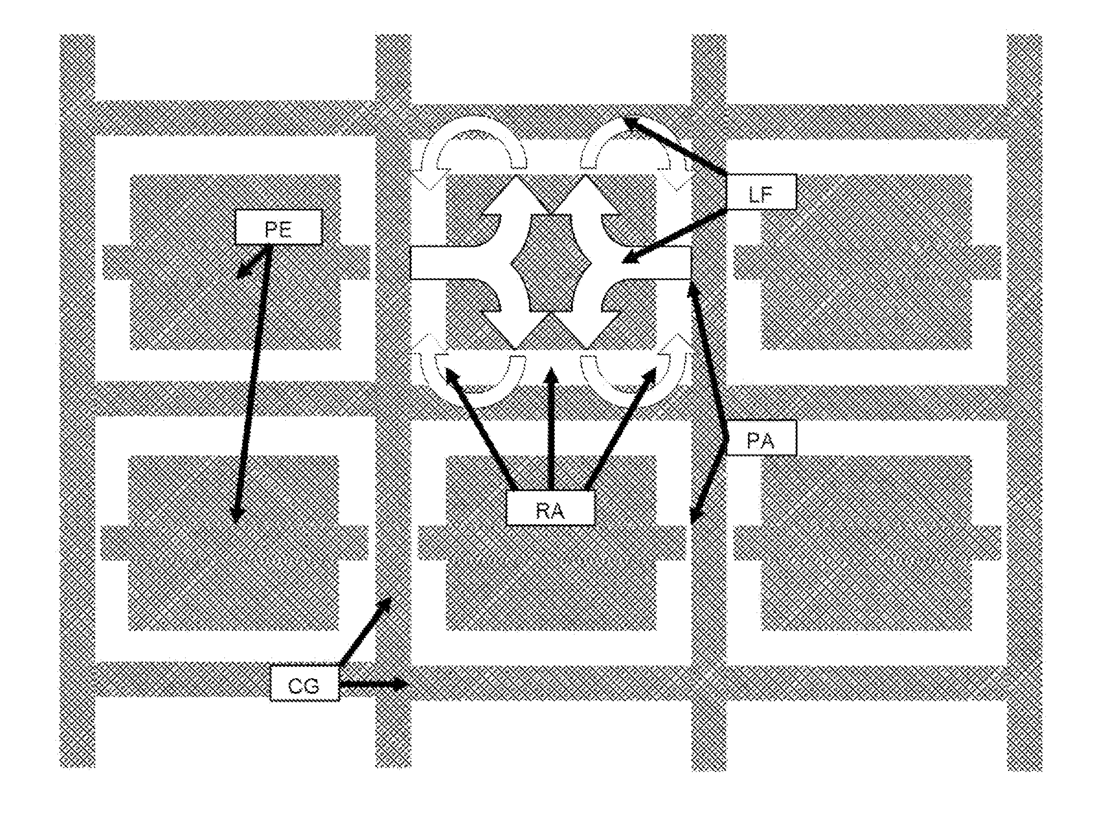
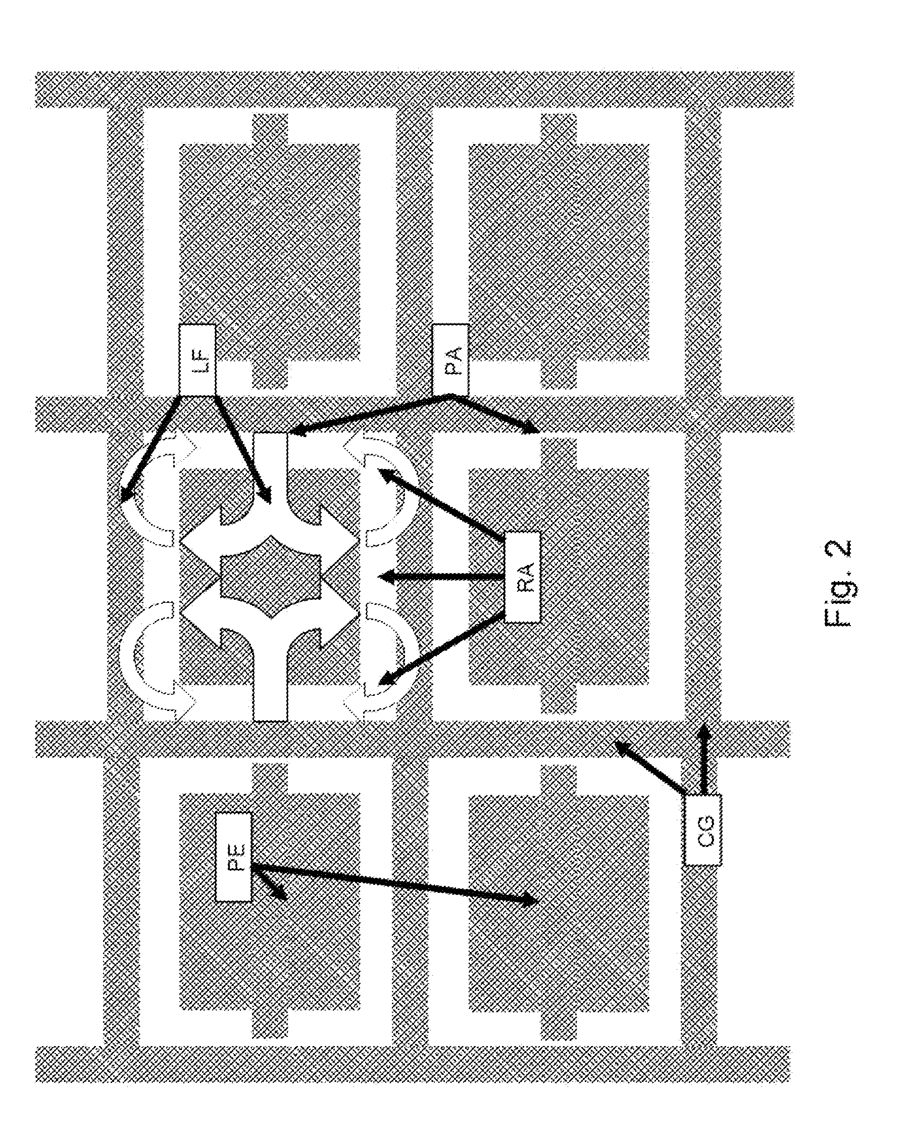
[0017]FIG. 2 shows a top view of pixels in which a fast liquid flow can be induced. The common grid or storage electrode is indicated by CG and the pixel electrode or field electrode by PE. The pumping area is referred to as PA, the release area as RA and the liquid flow is indicated by the arrows LF.
[0018]The electrode pattern is formed by applying a “common grid” or “common lines” (often referred to as “storage electrode”) CG, with pixel electrodes (also called “field electrodes”) PE placed in the “common grid” apertures or between the lines CG (see FIG. 1). Each pixel consists of an area that constitutes the “pump area” PA, which is an area where a small gap between the “common grid” CG creates a high electric field.
[0019]This field exerts a force o...
PUM
 Abstract
Description
Claims
Application Information
 - R&D
- Intellectual Property
- Life Sciences
- Materials
- Tech Scout
- Unparalleled Data Quality
- Higher Quality Content
- 60% Fewer Hallucinations
Browse by: Latest US Patents, China's latest patents, Technical Efficacy Thesaurus, Application Domain, Technology Topic, Popular Technical Reports.
© 2025 PatSnap. All rights reserved.Legal|Privacy policy|Modern Slavery Act Transparency Statement|Sitemap|About US| Contact US: help@patsnap.com


