Light-emitting device module and atomic oscillator
- Summary
- Abstract
- Description
- Claims
- Application Information
AI Technical Summary
Benefits of technology
Problems solved by technology
Method used
Image
Examples
first modification
2.1. First Modification
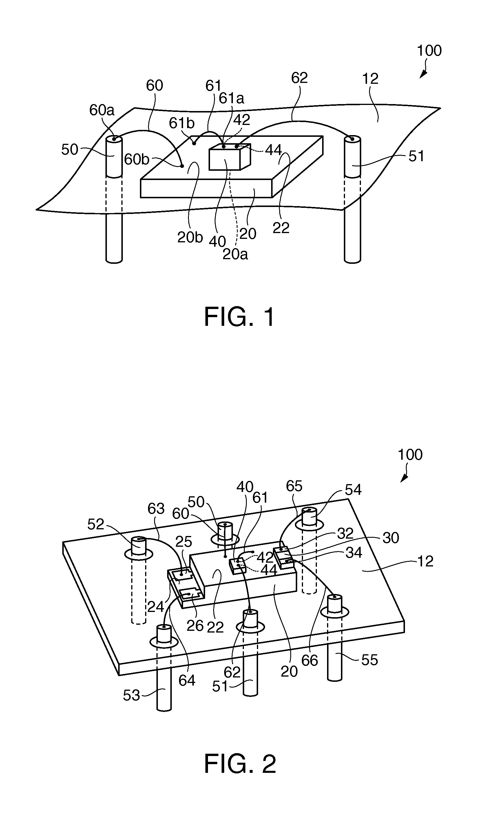
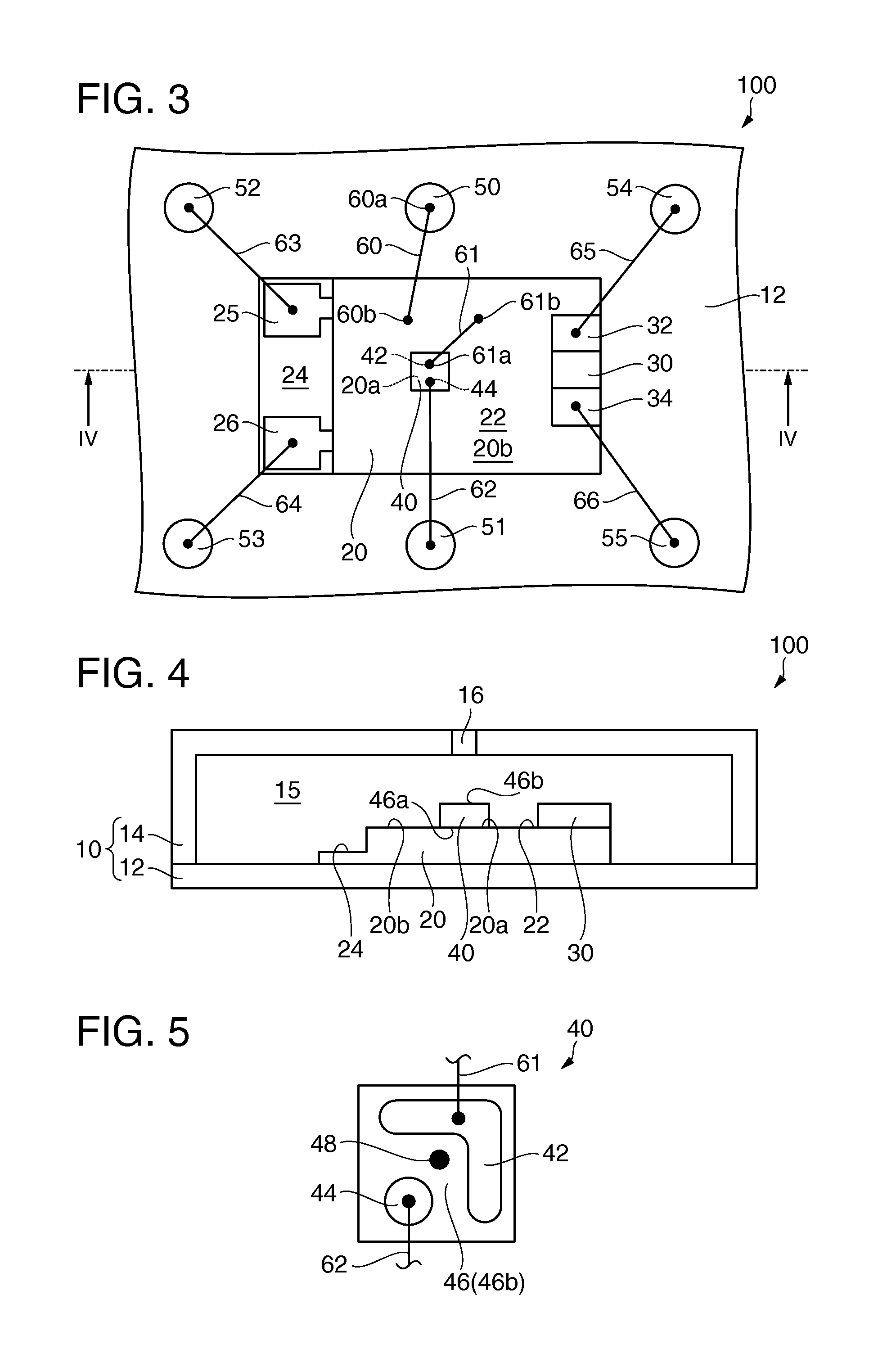
[0080]A light-emitting device module according to a first modification of this embodiment is explained with reference to the drawings. FIG. 6 is a plan view schematically showing a light-emitting device module 200 according to the first modification of this embodiment. FIG. 6 corresponds to FIG. 3.
[0081]In the following explanation, in the light-emitting device module 200 according to the first modification of this embodiment, members having functions same as the functions of the members of the light-emitting device module 100 according to this embodiment are denoted by the same reference numerals and signs. Detailed explanation of the members is omitted.
[0082]In the light-emitting device module 200, as shown in FIG. 6, the light-emitting device 40 is arranged on an imaginary straight line L in plan view. The imaginary straight line L is a straight line passing a center O of the temperature control surface 22 having a square (in an example shown in the figure,...
third modification
2.3. Third Modification
[0094]A light-emitting device module according to a third modification of this embodiment is explained with reference to the drawings. FIG. 9 is a perspective view schematically showing a light-emitting device module 400 according to the third modification of this embodiment. FIG. 9 corresponds to FIG. 7.
[0095]In the following explanation, in the light-emitting device module 400 according to the third modification of this embodiment, members having functions same as the functions of the members of the light-emitting device module 300 according to the second modification of this embodiment are denoted by the same reference numerals and signs. Detailed explanation of the members is omitted.
[0096]In the example of the light-emitting device module 300, as shown in FIG. 7, the second electrode 44 and the second terminal 51 are electrically connected via the wire 62. On the other hand, in the light-emitting device module 400, as shown in FIG. 9, the second electrode...
fourth modification
2.4. Fourth Modification
[0102]A light-emitting device module according to a fourth modification of this embodiment is explained with reference to the drawings. FIG. 10 is a perspective view schematically showing a light-emitting device module 500 according to the fourth modification of this embodiment. FIG. 10 corresponds to FIG. 9.
[0103]In the following explanation, in the light-emitting device module 500 according to the fourth modification of this embodiment, members having functions same as the functions of the members of the light-emitting device module 400 according to the third modification of this embodiment are denoted by the same reference numerals and signs. Detailed explanation of the members is omitted.
[0104]In the example of the light-emitting device module 400, as shown in FIG. 9, the other end 67b of the third wire 67 and the other end 68b of the fourth wire 68 are joined to the temperature control surface 22 having electrical conductivity. On the other hand, in the ...
PUM
 Abstract
Description
Claims
Application Information
 - R&D
- Intellectual Property
- Life Sciences
- Materials
- Tech Scout
- Unparalleled Data Quality
- Higher Quality Content
- 60% Fewer Hallucinations
Browse by: Latest US Patents, China's latest patents, Technical Efficacy Thesaurus, Application Domain, Technology Topic, Popular Technical Reports.
© 2025 PatSnap. All rights reserved.Legal|Privacy policy|Modern Slavery Act Transparency Statement|Sitemap|About US| Contact US: help@patsnap.com


