
Method for determining position of orthodontics mini-screw and apparatus thereof

a mini-screw and position determination technology, applied in dental surgery, dental tools, tomography, etc., can solve the problems of inconvenient user finding the appropriate location, fast orthodontic system, and difficulty in realizing desired orthodontic effects, and achieve the effect of accurate determination and increasing the success ra

Active Publication Date: 2013-08-01
INFINITT HEALTHCARE CO LTD
View PDF4 Cites 3 Cited by
  • Summary
  • Abstract
  • Description
  • Claims
  • Application Information

AI Technical Summary

Benefits of technology

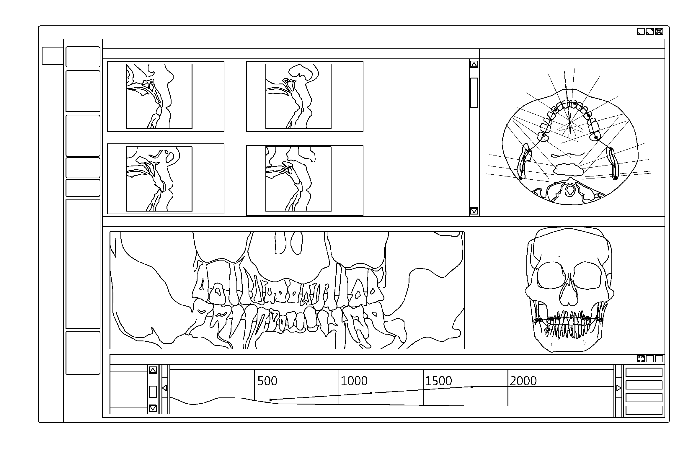
The present invention offers a method and apparatus for accurately determining the location of an orthodontic fastener, which can reduce the period of treatment and increase the success rate of orthodontic treatment. The invention involves computing bone density values of alveolar bone in the direction in which a fastener will be inserted and synchronizing user inputs with the computed bone density values. The interface allows easy setting of the optimum location for the fastener. This technology can help improve the precision of orthodontic treatment and enhance the overall effectiveness.

Problems solved by technology

However, this anchoring structure makes it difficult to realize desired orthodontic effects because the reaction force of the orthodontic force is exerted on the molar teeth, which are anchoring bases.
However, this fast orthodontic system is problematic in that when a fastener is inserted into a gap between the root of a tooth and the alveolar bone, the fastener is removed from the alveolar bone or touches a nerve in the root of the tooth over time because the location at which a fastener, for example, a mini-screw, is determined using a 2D image.
However, this method is problematic in that it is not suitable for a user finding the appropriate location at which a fastener, for example, a mini-screw, will be inserted because the user personally analyzes and uses data on an axial, sagittal or coronal 2D screen.

Method used


Image

  • Method for determining position of orthodontics mini-screw and apparatus thereof
  • Method for determining position of orthodontics mini-screw and apparatus thereof
  • Method for determining position of orthodontics mini-screw and apparatus thereof

Examples


Embodiment Construction

[0033]Embodiments of the present invention will be described in detail below with reference to the accompanying drawings. In the following description of the embodiments, if it is determined that a detailed description of a related known configuration or function may make the gist of the present invention vague, the detailed description will be omitted. However, the present invention is not limited to the embodiments. Meanwhile, throughout the accompanying drawings, like reference symbols denote like components.

[0034]A method and apparatus for determining the location of an orthodontic fastener in accordance with embodiments of the present invention will be described in detail below with reference to FIGS. 1 to 10.

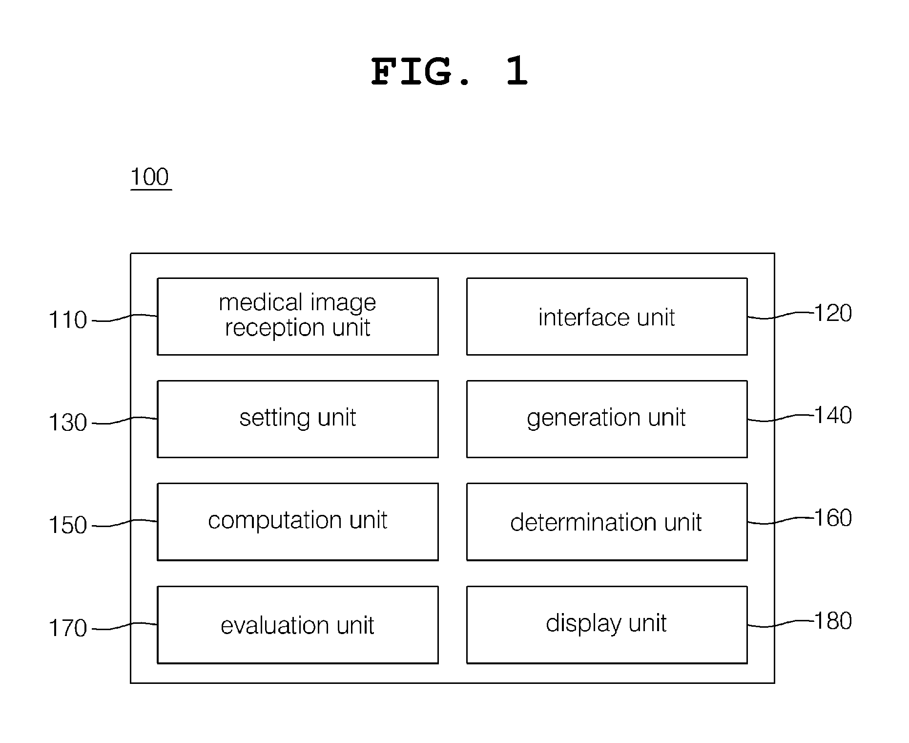
[0035]FIG. 1 illustrates the configuration of an apparatus 100 for determining the location of an orthodontic fastener in accordance with an embodiment of the present invention.

[0036]Referring to FIG. 1, the apparatus 100 for determining the location of an orthodontic fast...


PUM


Abstract

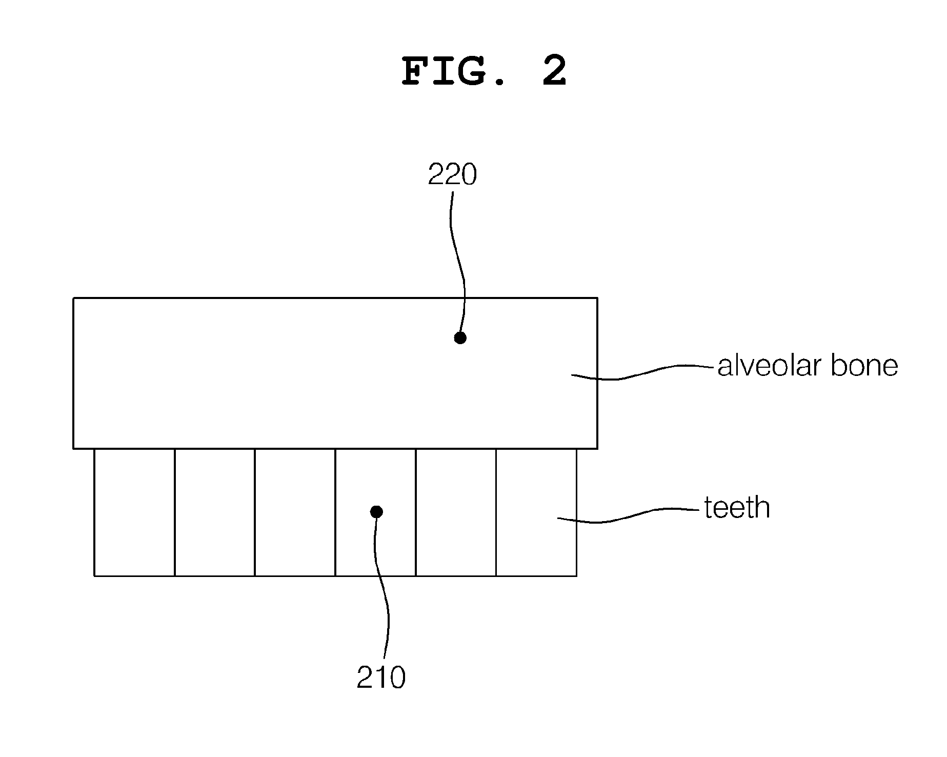
Disclosed herein are a method and apparatus for determining the location of an orthodontic fastener. In the method, a first location on a tooth and a second location on alveolar bone are set on a patient's medical image. Thereafter, a first rectilinear line including two points, that is, the set first and second locations, is generated. Thereafter, bone density values at the locations of the alveolar bone on the generated first rectilinear line are computed using the medical image. Finally, the location of the alveolar bone at which a first fastener is inserted is determined based on the computed bone density values.

Description

CROSS-REFERENCE TO RELATED APPLICATION[0001]This application claims under 35 U.S.C. §119(a) the benefit of Korean Application No. 10-2012-0009687 filed Jan. 31, 2012, which is incorporated herein by reference.TECHNICAL FIELD[0002]The present invention relates generally to the determination of the location at which an orthodontic fastener will be inserted and, more particularly, to a method and apparatus for determining the location of an orthodontic fastener that are capable of providing the appropriate location at which an orthodontic fastener will be inserted in order to perform orthodontic treatment that uses the orthodontic fastener, such as a mini-screw.BACKGROUND ART[0003]The life spans of people today are increasing continuously thanks to the improvement of life environments and the development of medical technology. Furthermore, recently, people have emphasized the aspect of the quality of life, in addition to the extension of life-spans. People's interest in the improvement...

Claims


Application Information

Patent Timeline
Patent Type & Authority Applications(United States)
IPC IPC(8): A61C7/00A61B6/03A61C8/00A61C7/02A61B6/12A61B6/14A61B6/00A61B6/51
CPCA61B6/03A61C7/02A61C7/002A61B6/5217A61C8/0096A61B6/032A61B6/14A61B6/12A61B6/463A61C1/084A61B6/4085G16H50/30A61B6/51A61C7/00A61C19/04
Inventor KIM, JIN KOOKHAN, JAE ILJEONG, JEONG WOON
Owner INFINITT HEALTHCARE CO LTD
Learn More