
Digital equalizing filters with fixed phase response

a technology of equalizing filter and phase response, applied in the direction of impedence network, digital signal tone/bandwidth control, transducer casing/cabinet/support, etc., can solve the problems of linear phase filter and undesired properties

Active Publication Date: 2013-08-01
HARMAN BECKER AUTOMOTIVE SYST
View PDF2 Cites 6 Cited by
  • Summary
  • Abstract
  • Description
  • Claims
  • Application Information

AI Technical Summary

Benefits of technology

This patent describes an equalization filter structure for audio signals in an audio system. The filter structure includes two shelving filters, each with different phase characteristics determined by a cut-off frequency and Q factor. The filters are connected in series and each has a fourth order low-pass filter and a fourth order high-pass filter. These filters provide the same output signal by adding the filtered signals. The method uses the same filters as the structure but with different cut-off frequencies and Q factors to achieve different equalization effects. The technical effect of this patent is to provide a flexible and effective equalization filter structure for audio signals in an audio system.

Problems solved by technology

However, many classes of digital filters distort the magnitude response when designed to provide a well-defined phase response (and vice versa) as phase and magnitude cannot be set independently.
Linear phase filters have, however, some undesired properties which may give rise to adverse effects known as “pre-ringing” and “temporal diffusion”.

Method used


Image

  • Digital equalizing filters with fixed phase response
  • Digital equalizing filters with fixed phase response
  • Digital equalizing filters with fixed phase response

Examples


Embodiment Construction

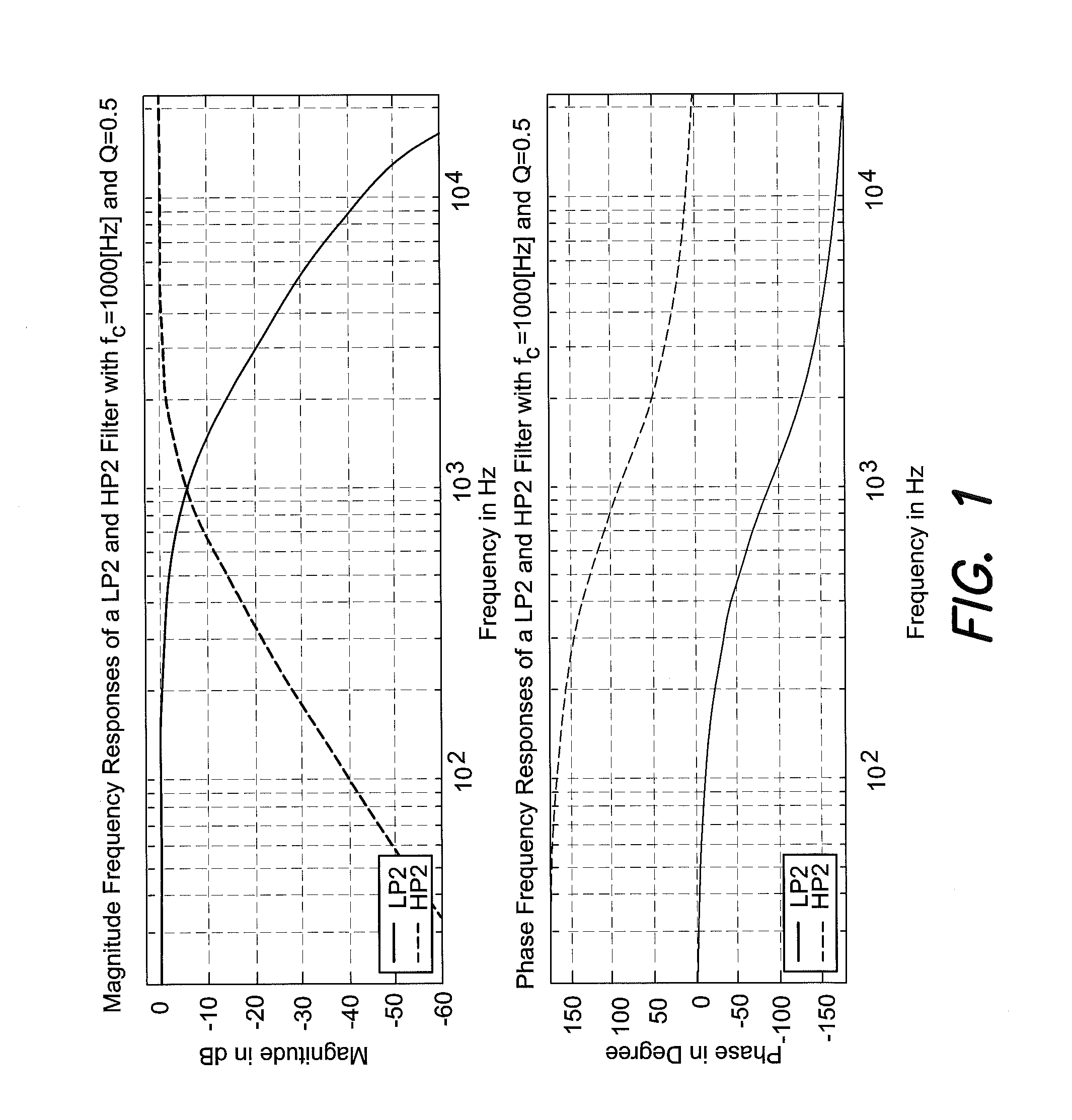
[0019]For the use as equalization filters (digital or analog) filter structures should pro-vide a few parameters via which the filter characteristic can be adjusted. That is, the magnitude response over frequency may be adjusted by tuning only one or a few parameters. One example of commonly used filters are second order low-pass and high-pass filters which may be characterized by the following parameters: cut-off frequency (symbol fC), Q factor (symbol Q), and broadband gain (symbol G). In a digital implementation such filters are often implemented as biquadratic infinite impulse filters (biquad IIR filters). FIG. 1 illustrates the bode plots of a second order low-pass and a second order high-pass filter, each filter having a broadband gain G of zero decibel (G=1 or G=0 dB), a cut-off frequency fC of one kilohertz (fC=1 kHz) and a Q factor of 0.5. It should be noted that the phase responses of the two filters (low-pass and high-pass) are equal except for the constant phase shift (o...


PUM


Abstract

An equalization filter structure for filtering an audio signal within an audio system is disclosed. The equalization filter comprises a first and a second shelving filter each having a fixed first and a fixed second phase response, each of which is determined by a respective cut-off frequency and Q factor which represent the transfer characteristic of the corresponding shelving filter. The first and the second shelving filters are coupled in series and each shelving filter comprises at least one fourth order low-pass filter having a cut-off frequency, a Q factor and a first broadband gain and further at least one fourth order high-pass filter having a second broadband gain and the same cut-off frequency and the same Q factor as the low-pass filter. The fourth order low-pass filter and the fourth order high-pass filter are connected in parallel, such that both filters receive the same input signal and the corresponding filtered signals are summed to form a respective shelving filter output signal. Each fourth order low-pass and high-pass filter is composed of a cascade of two second order low-pass or high-pass filters, respectively, and each second order filter has the same cut-off frequency and Q factor as the corresponding shelving filter.

Description

CLAIM OF PRIORITY[0001]This patent application claims priority from EP Application No. 11 194 115.9 filed Dec. 16, 2011 which is hereby incorporated by reference.FIELD OF TECHNOLOGY[0002]The invention relates to digital equalization filters, which may be used for the purpose of sound tuning or equalization of audio systems so as to achieve a sound impression desired by the listener(s).RELATED ART[0003]Modern sound systems which are used, for example, in automobiles, typically include a plurality of single loudspeakers configured into highly complex loud-speaker arrays located at different positions of a listening room (e.g., in a passenger compartment of a vehicle). Such sound systems used to be tuned (i.e., optimized) “manually” by acoustic engineers individually for each room or type of room. Usually the tuning is performed subjectively based on the experience and “trained” hearing of the acoustic engineers. The acoustic engineers may therefore use analog or digital filter circuit...

Claims


Application Information

Patent Timeline
IPC IPC(8): H03G5/00
CPCH03H17/0264H03H17/0294H04S7/307H03G5/165H03G5/00H03G5/005H03H2017/0297
Inventor CHRISTOPH, MARKUS
Owner HARMAN BECKER AUTOMOTIVE SYST
Learn More