
System and method for measuring video quality degradation using face detection

a technology of video quality and detection method, applied in the field of video quality degradation detection detection, can solve the problems of inability to detect video quality degradation in real time (i.e., in service), measurement is taken at the media layer, and is typically computationally intensive, and achieves the effect of few speakers and low amount of motion

Active Publication Date: 2013-08-01
AVAYA INC
View PDF5 Cites 4 Cited by
  • Summary
  • Abstract
  • Description
  • Claims
  • Application Information

AI Technical Summary

Benefits of technology

The present invention relates to detecting video quality degradation in applications such as video conferencing. The invention uses face detection as a video quality metric, which focuses on video content that is easy for subjective users to notice errors in. The invention measures how the location of a box around the faces differs between sent and received frames, which is a lightweight indicator of video quality. The difference in box location between sent and received frames indicates a problem with service quality that requires corrective action, such as finding a face in the wrong place. The invention provides a method and system for detecting video quality degradation by locating reference features, calculating reduced reference features, receiving transmitted video stream, calculating a distance between the reduced reference features, and detecting video quality degradation when the calculated distance exceeds a predetermined threshold. The technical effect of the invention is to provide a reliable and efficient means to assess video quality in real-time applications, particularly in video conferencing.

Problems solved by technology

While some video quality metrics are known in the background art, a standard metric that accurately reflects user opinion with a level of overhead that is appropriate for real-time monitoring and QoS assurance is not known.
The measurements are taken at the media layer and are typically computationally intensive.
As a result, these techniques are not suitable for real-time (i.e., in-service) video quality monitoring.
While the comparison of only the extracted features reduces the computational overhead, it may still be computationally intensive to extract the features from the source video.
As such, the reduced features typically incur notable transmission overheads for real-time operations.
Transmitting the extracted VQM features incur significant overhead for in-service monitoring.
However, the pixel-based techniques cannot handle video sequences with unanticipated distortions.
In addition, the pixel-based techniques cannot distinguish between impairments due to the network or impairments already in the original video sequence.
Furthermore, any such MOS function needs to account for error concealment capabilities of the decoder.
A uniform level of packet loss presented to various video decoders may result in varying levels of quality among the video decoders.
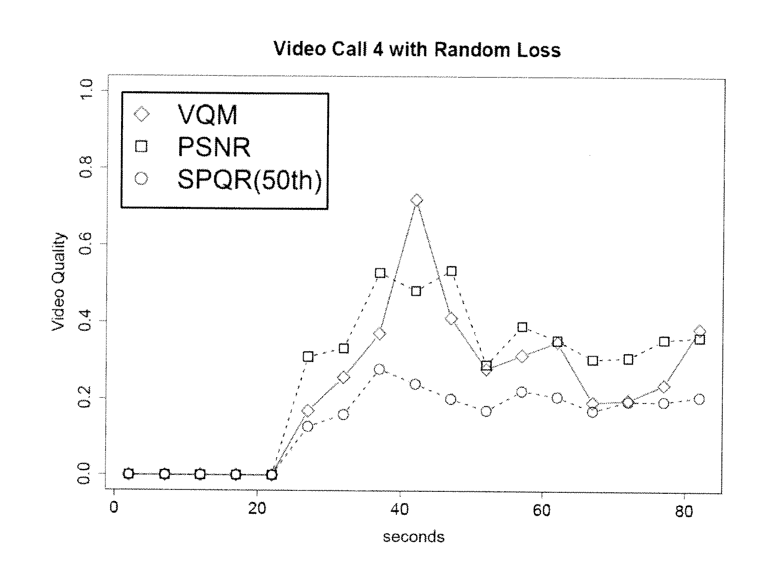
However, PSNR and VQM are not suitable for real-time (i.e., in-service) operations due to computational and transmission overheads.
For example, if the difference in box locations shows that a face has been found in the wrong place, by more than a de minimus amount, then the difference is an indication of a severe problem.

Method used


Image

  • System and method for measuring video quality degradation using face detection
  • System and method for measuring video quality degradation using face detection
  • System and method for measuring video quality degradation using face detection

Examples


Embodiment Construction

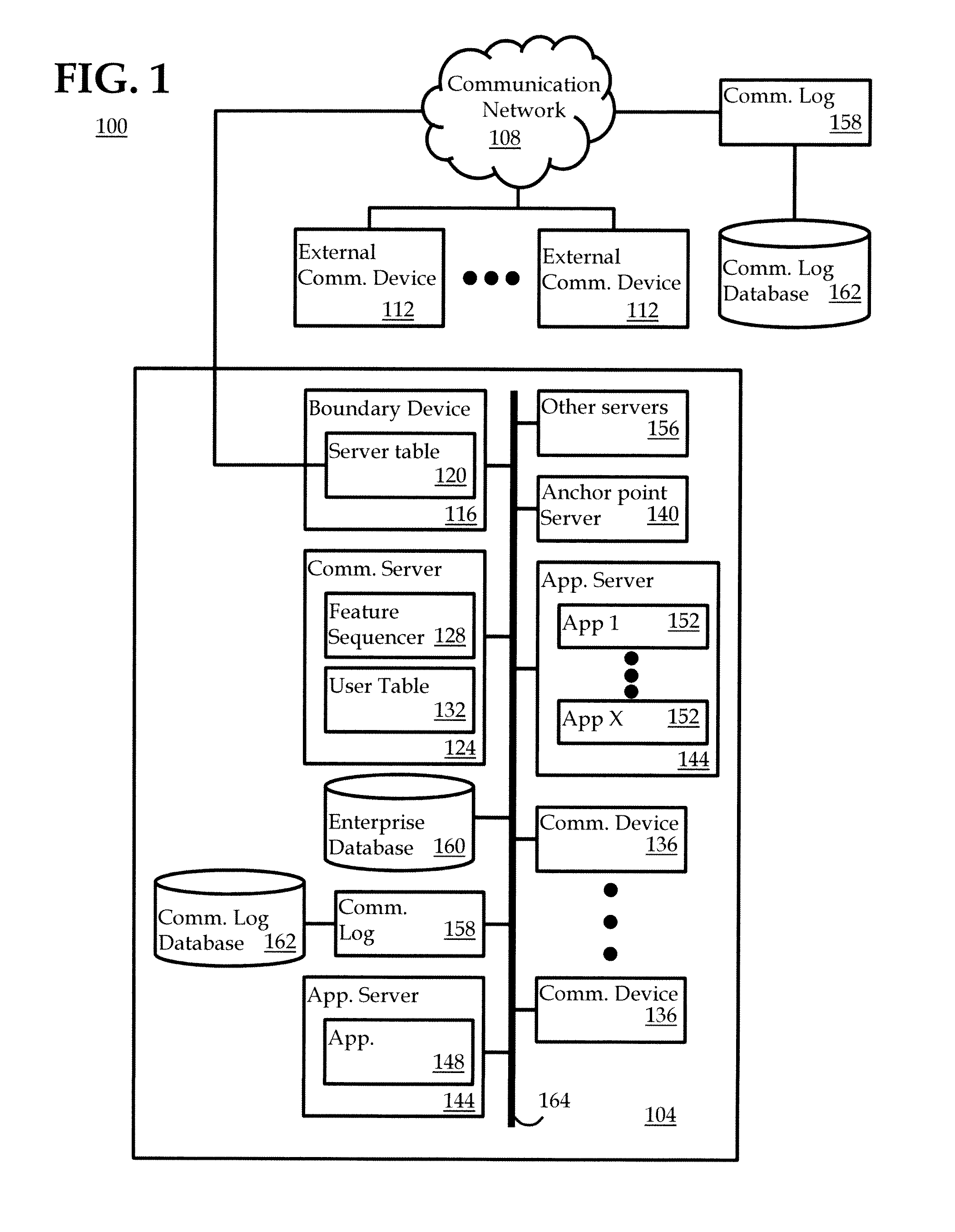
[0030]The disclosure will be illustrated below in conjunction with an exemplary communication system. Although well suited for use with, e.g., a system using a server(s) and / or database(s), the disclosure is not limited to use with any particular type of communication system or configuration of system elements. Those skilled in the art will recognize that the disclosed techniques may be used in any communication application in which it is desirable to utilize computationally-light methods to detect video degradations.

[0031]The exemplary systems and methods of this disclosure will also be described in relation to video conferencing software, modules, and associated video conferencing hardware. However, to avoid unnecessarily obscuring the present disclosure, the following description omits well-known structures, components and devices that may be shown in block diagram form, are well known, or are otherwise summarized.

[0032]Embodiments in accordance with the present invention address...


PUM


Abstract

System and method to detect video quality degradation in a video stream received by a telecommunications endpoint, the method including: locating reference features characteristic of content in the received video stream; calculating reduced reference features from the located reference features; receiving reduced reference features of a transmitted video stream, the transmitted video stream corresponding to the received video stream; calculating a distance between the reduced reference features in the received video stream and the reduced reference features of the transmitted video stream; and detecting video quality degradation when the calculated distance exceeds a predetermined threshold.

Description

CROSS-REFERENCE TO RELATED APPLICATIONS[0001]This application claims the benefit of U.S. Provisional Patent Application Ser. No. 61 / 591,019, filed on Jan. 26, 2012, and the benefit of U.S. Provisional Patent Application Ser. No. 61 / 614,617, filed on Mar. 23, 2012, the entire content of which are hereby incorporated by reference in its entirety.BACKGROUND[0002]1. Field of the Invention[0003]Embodiments of the present invention generally relate to detection of degraded quality of a video transmission, and, in particular, to a system and method for using face detection to detect degraded video quality.[0004]2. Description of Related Art[0005]Improving and maintaining high video quality during adverse network conditions is important for wide deployments of video over IP networks that inherently lack end-to-end quality of service (“QoS”) guarantees. Application-layer quality assurance is typically achieved by monitoring video quality in real-time, detecting degradation, and taking approp...

Claims


Application Information

Patent Timeline
IPC IPC(8): H04N17/00
CPCH04N7/148G06K9/036G06K9/00228H04N17/004G06V40/161G06V10/993
Inventor KRISHNAKUMAR, ANJUR S.KARACALI-AKYAMAC, BENGI
Owner AVAYA INC
Learn More