Method and Equipment for Reinforcing a Substance or an Object with Continuous Filaments

a technology of continuous filaments and materials, applied in the field of improving the process of reinforcing a substance or an object with continuous filaments, can solve the problems of affecting the quality of the product, etc., and achieves the effects of high operation speed, short space, and high performan

Inactive Publication Date: 2013-08-01
3B FIBERGLASS
View PDF0 Cites 9 Cited by
  • Summary
  • Abstract
  • Description
  • Claims
  • Application Information

AI Technical Summary

Benefits of technology

[0117]An advantage of the invention is that it may be practiced upon two or more fiber strands at once that are spread widely and dispersed uniformly by using a spreader assembly comprising two or more spreader units having one or more than one of filament passageways disposed one above the other or side by side. It is, with proper combination therefore, also suitable for manufacturing a composite structure comprising a large amount of reinforcing fiber. Thus, several spreader units having one or more than one of filament passageways may be combined together and placed in such a combination as to obtain desired width for the spread fibers and at the same time desired amount of glass % by weight required for the in-line subsequent processing into a composite reinforced structure. Furthermore, by connecting each inlet for air of the spreader units to an air compressor by conventional means, all spreader units may share one air supply.
[0118]FIGS. 11 to 14 illustrate an embodiment of a spreader assembly comprising four spreader units, two external units 2a, 2d and two inner units 2b, 2c, which are disposed one above the other. Although the individual spreader units may have different structures adapted for use in combination with each other, each spreader unit, preferably has the same structure as described above and illustrated in FIGS. 1 to 9. The base 26a of the upper external unit 2a is in contact with the cover 25b of the upper inner unit 2b which is just underneath. The upper external unit 2a mounted on the upper inner unit 2b is horizontally shifted in the direction of fiber movement (represented with the arrow A in FIG. 12) so that the air inlet 241b of the upper inner unit 2b is uncovered and can be connected to a compressed air supply. Each air inlet 241a, 241b may be connected to a compressed air supply by a conventional means (not shown). A second inner unit 2c is mounted under the upper inner unit 2b without any horizontal shift. And a second external unit 2d is mounted under the second inner unit 2c and shifted horizontally in the direction of the fiber movement. According to other embodiments more than four spreader units may be stacked.
[0119]FIGS. 15 to 23 illustrate another preferred embodiment of a spreader assembly 2 according to the present invention comprising four spreader units, 2e, 2f, 2g and 2h. The upper spreader unit 2e comprises a cover 25e and a base 26e which are joined together by a conventional means such as screws or clamps (not shown). The cover 25e of the spreader unit 2e comprises two through holes 242e and 242f corresponding to air passages as shown in FIGS. 16, 17 and 19 to 21. One through hole 242e is connected to the air outlet 24e of spreader unit 2e and the other 242f is connected to the through hole 242f disposed in the base 26e of unit 2e which has a structure similar to the structure of the base 26a as described above. The hole 242e allows the supply of air into the passageway 21e of the upper spreader unit 2e and the hole 242f allows the supply of air into the passageway 21f of an inner unit 2f underneath. The hole 242f, therefore, passes through the cover 25e, the base 26e and the cover 25f. The base 26f of the inner unit 2f comprises a groove 21f which has a structure similar to the structure of the groove 21e of the base 26e but is shifted into a lateral direction in order to avoid overlapping of the position of the through hole 242f with the one 242e of unit 2e. The inner units 2f and 2g are joined together with their respective bases 26f and 26g. FIG. 39 shows a snap shot of this spreading using the spreader assembly comprising four spreader units. It shows that four fiber strands are opening and widely spreading into individual filaments.
[0120]FIGS. 24 to 36 illustrate another preferred embodiment of the spreader assembly 2 according to the present invention comprising three spreader units, 2i, 2j and 2k, wherein each unit has two passageways 21 and two air though holes 242. This assembly can provide a plurality of separated and spread filaments in a short space at high operation speed. Each spreader unit, 2i, 2j and 2k, comprises a cover, 25i, 25j and 25k, and a base, 26i, 26j and 26k, which are joined together by a conventional means such as screws or clamps. Each unit, 2i, 2j and 2k, comprises a pair of passageways for filaments, 21i, 21j and 21k, placed in parallel to each other. The pairs of passageways 21i and 21j of units 2i and 2j are shifted in a lateral direction in order to avoid overlapping of the position of the through holes 242i of unit 2i with the one 242j of unit 2j. The pair of passageway 21k of the unit 2k is positioned in the middle of the unit 2k. The cover 25i of the spreader unit 2i comprises four through holes 242i and 242j corresponding to air passages. The two through holes 242i are connected to the passageways 21i via the air outlet 24i relatively and the other through holes 242j are connected to the passageways 21j via the through holes 242j relatively. The holes 242j pass through the cover 25i, the base 26j and the cover 25j. The cover 25k of the spreader unit 2k comprises two through holes 242k corresponding to air passages. The through holes 242k are connected to the passageways 21k via the air outlet 24k relatively. The inner unit 2j and the bottom unit 2k are joined together with their respective bases 26j and 26k.
[0121]According to the invention, the fiber strand may be separated and spread into individual fibers so that it may be directly or indirectly coated, soaked, submerged, dipped, infused or impregnated with substances e.g., solids such as powders, or liquids such as solutions, emulsions, dispersions of polymers, molten polymers, waxes, to form a composite structure. For example, the spread fibers, could be wound on a core and later infused with a substance, or directly impregnated with a resin matrix substance.
[0122]FIG. 40 schematically shows preferred embodiment of the process equipment according to the present invention, for manufacturing a composite structure reinforced with continuous fibers comprising the spreader assembly of the present invention. Fiber strands 5 may be supplied from fiber strand spools and fed through a spreader assembly 2 according to the present invention by a conventional pulling mechanism of subsequent process 13. The resulting fiber-opened strand 7 may be directed into an impregnation assembly 3 and subjected to an impregnation with impregnation material brought from a source such as an extruder 10. The resulting impregnated fiber strand 9 may be shaped to have a desired shape with a shaping die 11, such as a round strand, rod, ribbon, tape, plate, tube or any other special shape. The resulting product 9 may be cooled by a cooling means 12 or allowed to solidify or cure. The cooled, solidified or cured profiles may be cut to desired lengths. In the alternative, the resulting product 9 may be wound into a product such as pipe, cylinder, tube and panel, before cooling, solidification or curing. Also a readily formed rod may be cut to desired length with 14 using a cutter or a pelletizer to produce reinforced pellets which can be subsequently molded into composite parts. Such pellets with majority of fibers impregnated can disperse well within the matrix to be reinforced and lead to high performance composites even when molded at milder shear conditions. The obtained long fiber reinforced composite structure comprises reinforcing fibers which may be well impregnated with the impregnating material.

Problems solved by technology

The speed of the process can be hindered or limited by the suction part of the process.
Accordingly, using rolls or bars to separate fiber bundles has limitations, and is not well suited for delicate fibers, particularly when operating at relatively high speeds.
Thus, the stuck array of the single modules becomes much larger-in scale and more complicated in structure.
This apparatus, however, can not effectively open and spread a tightly packed fiber strand with the given gas jet system.

Method used


Image

  • Method and Equipment for Reinforcing a Substance or an Object with Continuous Filaments
  • Method and Equipment for Reinforcing a Substance or an Object with Continuous Filaments
  • Method and Equipment for Reinforcing a Substance or an Object with Continuous Filaments

Examples


example 1

[0128]A spreader assembly according to the present invention was arranged in a manner to have one passageway, enabling one inlet opening for glass fiber strands (SE4220 direct roving).

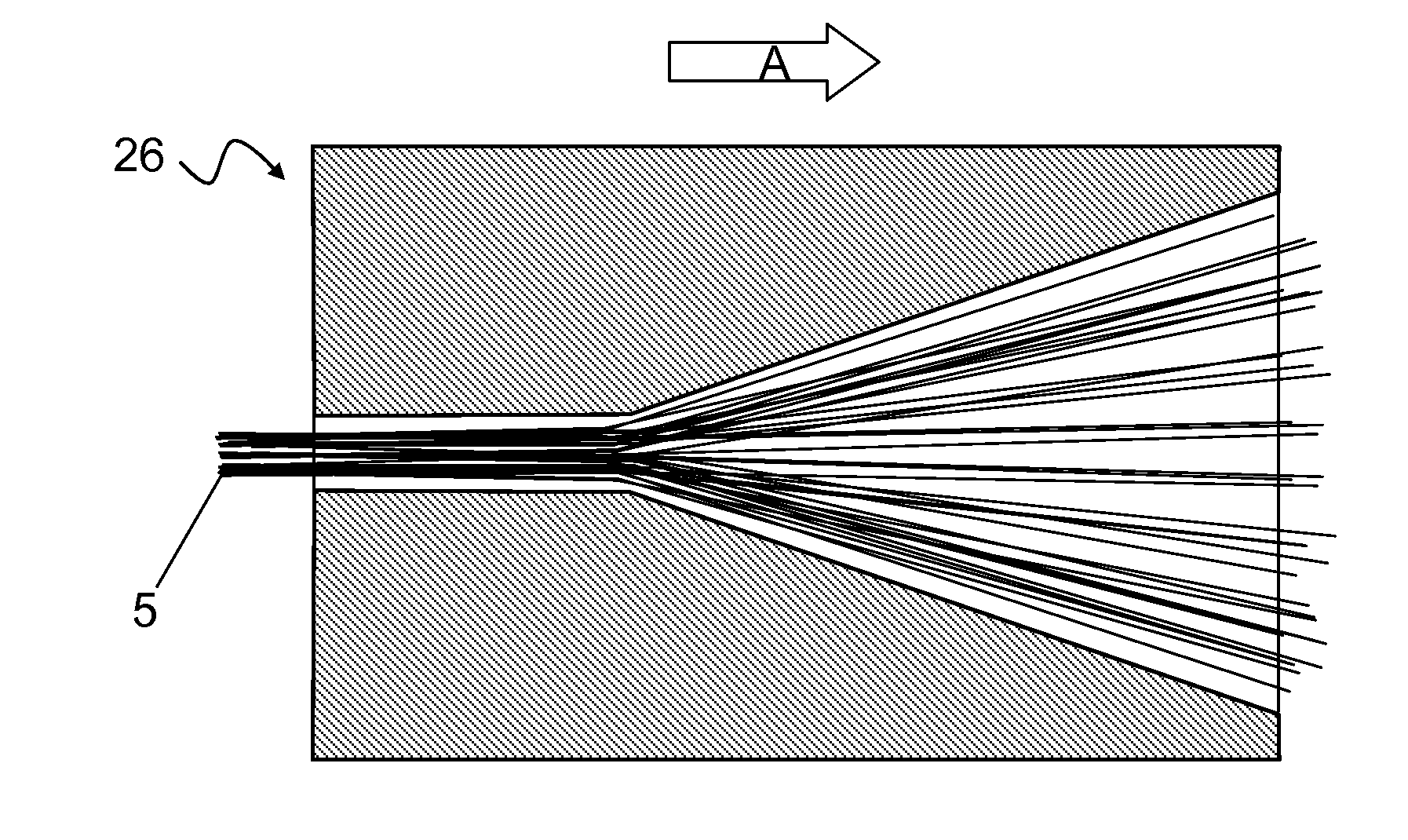
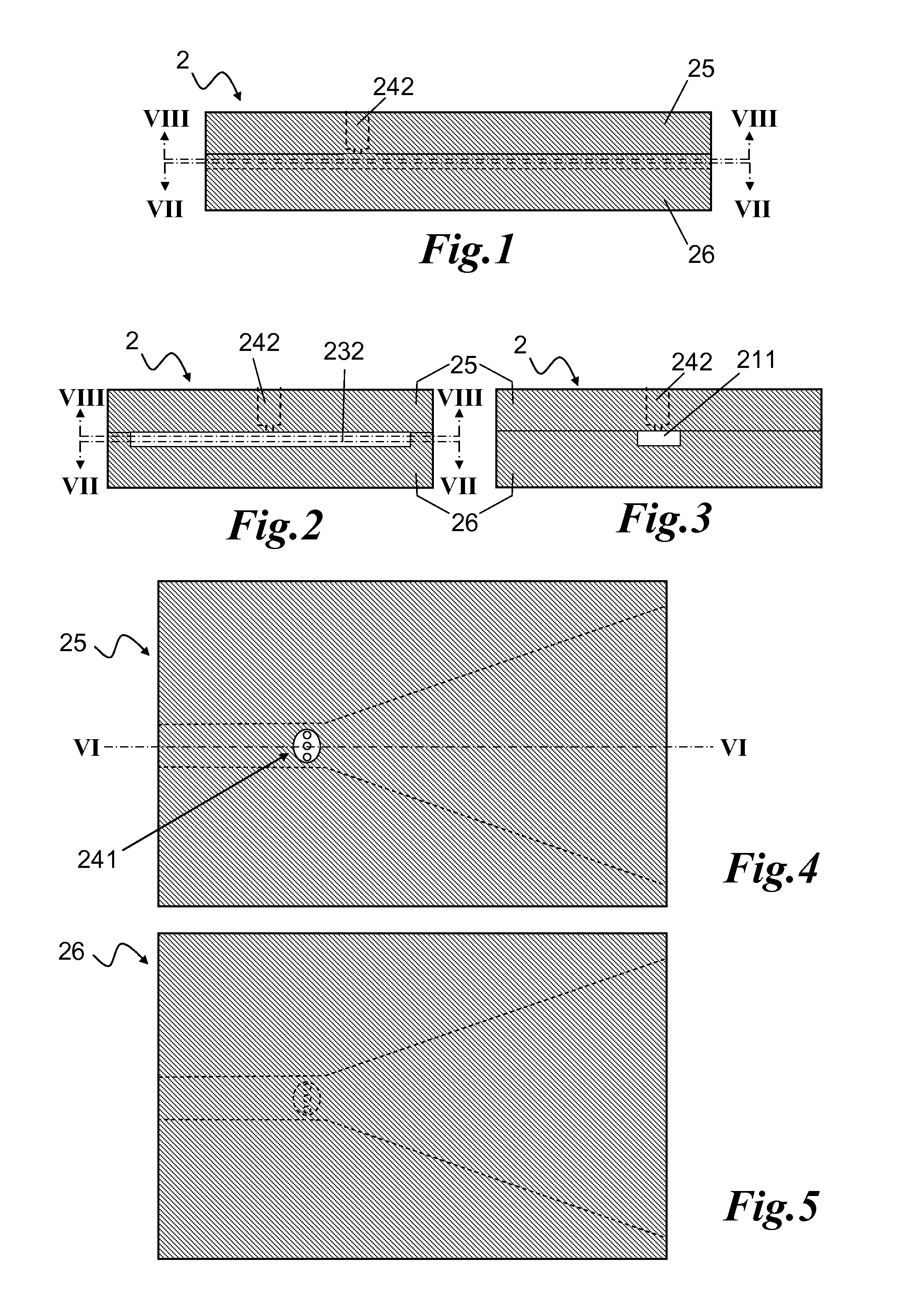
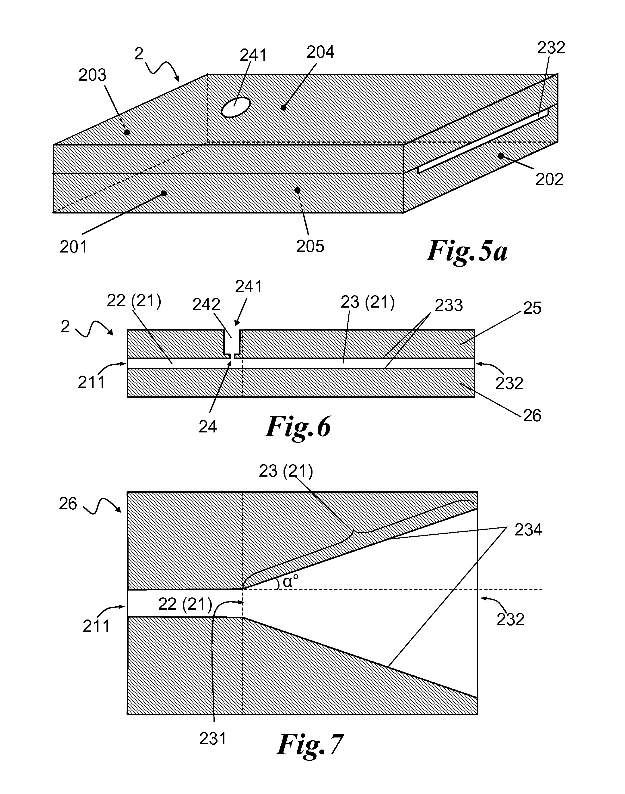
[0129]The passageway comprised an inner channel of rectilinear shape and a divergent zone and had a total passageway length of 60 mm, with the inner channel having dimensions of 30 mm×6 mm×0.6 mm followed immediately by the divergent zone having 30 mm in length with a divergence angle of about 26.6°, leading to dimensions of 30 mm×0.7 mm for the exit. The strand went through the inlet opening of 6 mm×0.5 mm, which was also the start of the inner channel of rectilinear shape of the passageway, and one exit end of 30 mm×0.7 mm, which was also the exit of the divergent zone of the passageway. The air, at 0.8 bar pressure, was supplied to the passageway through an air through hole leading to the inner channel of the passageway. The air through hole led to three finer holes of 1 mm diameter each, arranged a...

example 2

[0130]A spreader assembly according to the present invention was arranged in manner to have four passageways, enabling four inlets for glass fiber strands (SE4220 direct roving). Each of the four passageways comprised an inner channel of rectilinear shape and a divergent zone and had a total passageway length of 60 mm, with the inner channel having dimensions of 20 mm×6 mm×0.6 mm followed immediately by the divergent zone of 40 mm in length with a divergence angle of about 20.6°, leading to dimensions of 30 mm×0.7 mm for the exit. Each strand went through one inlet opening of 6 mm×0.5 mm, which was also the start of the inner channel of rectilinear shape of the passageway, and one exit end of 30 mm×0.7 mm, which was also the exit of the divergent zone of the passageway. The air, at 1.0 bar pressure, was distributed to the four passageways through their respective air through holes. Each air through hole led to three finer holes of 1 mm diameter each, arranged across the channel widt...

example 3

[0131]A spreader assembly according to the present invention was arranged in a manner to have six passageways, enabling six inlet openings for glass fiber strands (SE4220 direct roving). Each of the six passageways comprised an inner channel of rectilinear shape and divergent zone and had a total passageway length of 60 mm, with the inner channel having dimensions of 20 mm×6 mm×0.6 mm followed immediately by the divergent zone of 40 mm in length with a divergence angle of about 20.6°, leading to dimensions of 30 mm×0.7 mm dimensions for the exit. Each strand went through one inlet opening of 6 mm×0.5 mm, which was also the start of the inner channel of rectilinear shape of the passageway, and one exit end of 30 mm×0.7 mm, which was also the exit of the divergent zone of the passageway. The air, at 1.5 bar pressure, was distributed to the six passageways through their respective air through holes. Each air through hole led to three finer holes of 1 mm diameter each, arranged across t...


PUM

PropertyMeasurementUnit
angleaaaaaaaaaa
angleaaaaaaaaaa
angleaaaaaaaaaa

Abstract

The present invention provides a method of reinforcing a substance or an object with continuous filaments comprising the steps of (a) supplying a fiber strand from a source of fiber strands, (b) passing said fiber strand horizontally through a passageway (21), (c) subjecting said fiber strand to a fluid such as air flow, within a channel (22) of rectilinear shape having an oblong cross-section, at an angle (γ) substantially perpendicular with respect to the moving direction of the filaments so as to separate said fiber strand into a plurality of smaller strands or individual filaments, and then (d) pulling said separated strands and / or individual filaments horizontally through a divergent zone (23), wherein the area of its exit end (232) is larger than the one of its entrance end (231) and has an oblong cross-section, so as to spread said strands and / or filaments along its diverging wall in a plane. Thus, the present invention proposes an improved frictionless solution to spread the fiber strand at higher speeds with a newly designed and simple apparatus as well as an improved process for reinforcing a substance or an object with continuous filament.

Description

TECHNICAL FIELD OF THE INVENTION[0001]The present invention relates to an improved process of reinforcing a substance or an object with continuous filaments arranged substantially parallel to each other, in particular a process which comprises the steps of opening and spreading a strand or bundle of fibers into smaller strands and / or individual filaments and arranging them in a plane uniformly using a fluid stream, such as compressed air. The present invention also relates to a spreader assembly and to a process equipment for performance of said improved process. The invention is particularly well suited for, but not limited to, various glass fiber applications, including the production of parts or products consisting of continuous reinforced polymer structures in particular.BACKGROUND OF THE INVENTION[0002]Continuous fibers may be used as reinforcement material for a matrix substance such as polymer matrix, said fibers being suitably impregnated therewith. Continuous fibres may fur...

Claims


Application Information

Patent Timeline
Patent Type & Authority Applications(United States)
IPC IPC(8): B29C70/54B29C48/05B29C48/32
CPCB29B15/122B29C47/0014B29C47/0019B29C47/0023B29C47/02B29B15/12B29C47/20B29C70/523B29C70/543B29B15/14B29C47/025B29C48/05B29C48/15B29C48/07B29C48/09B29C48/154B29C48/32Y10T428/249921D01D11/02D02J1/18B65H51/005
Inventor KASHIKAR, SANJAY P.
Owner 3B FIBERGLASS
Why Eureka
Try Eureka