
Drive System for a Head Clamp for Use in Imaging by Magnetic Resonance and X-Ray

a technology of which is applied in the field of driving system for a head clamp for use in imaging by magnetic resonance and x-ray, can solve the problems of not being able to meet the requirements of a head clamp, the arrangement is not suitable for medical team intervention, etc., and achieves the effects of reducing the visibility of the device, minimizing the attenuation of the device, and minimizing the impact of the image of the body's anatomy

Active Publication Date: 2013-07-25
DEERFIELD IMAGING INC
View PDF4 Cites 30 Cited by
  • Summary
  • Abstract
  • Description
  • Claims
  • Application Information

AI Technical Summary

Benefits of technology

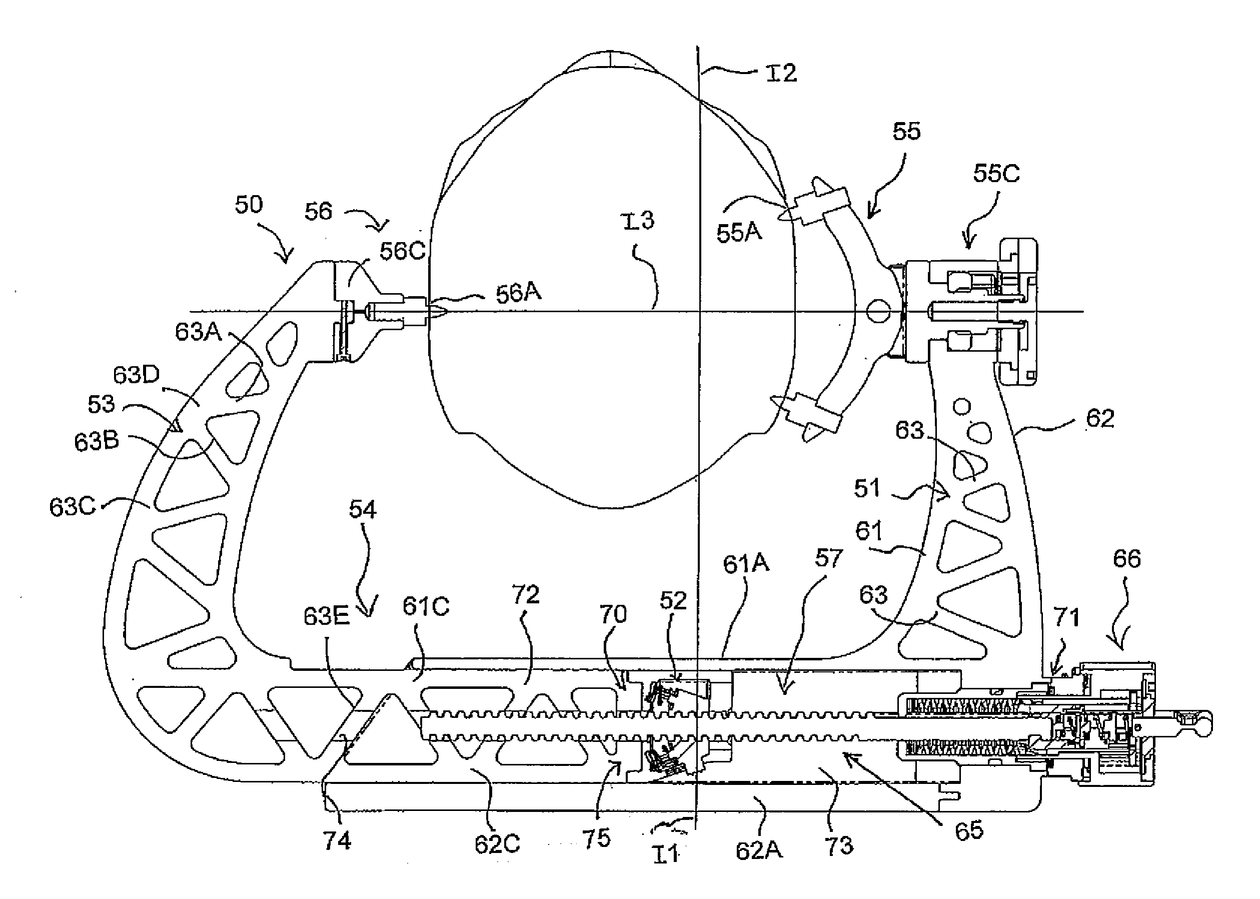
This patent describes a new device for fixing a patient's head in place during X-ray imaging. The device is designed to be very clear in the images, with most of the parts placed in a way that they don't interfine with the X-Ray images. The device is made from a material called PEEK, which is very thin and will not cause problems with the images. The device has two main adjustment mechanisms, one for coarse adjustment and one for fine adjustment. These mechanisms are combined into one drive system, which is located in the base of the skull clamp and is designed to be very ergonomic and easily adjusted. The user's hand wheel is designed to combine the functions of both the coarse adjustment ratchet plunger and the torque screw, making it easier to use. Overall, this new device simplifies the process of fixing a patient's head in place during X-ray imaging and improves the quality of the images obtained.

Problems solved by technology

However this arrangement is not suitable for interventions by the medical team since the presence of the machines restricts access to the patient.
However up to now it has not been possible with a head clamp to meet the requirements of radio-lucence required by FDA where the attenuation of the device when present in the X-ray image must be less than a factor of 2.3 mm of aluminum equivalent, that is the attention must be less than that of 2.3 mm of aluminum.

Method used


Image

  • Drive System for a Head Clamp for Use in Imaging by Magnetic Resonance and X-Ray
  • Drive System for a Head Clamp for Use in Imaging by Magnetic Resonance and X-Ray
  • Drive System for a Head Clamp for Use in Imaging by Magnetic Resonance and X-Ray

Examples


Embodiment Construction

[0089]The following description is taken from the above PCT application and is included for completeness of disclosure herein.

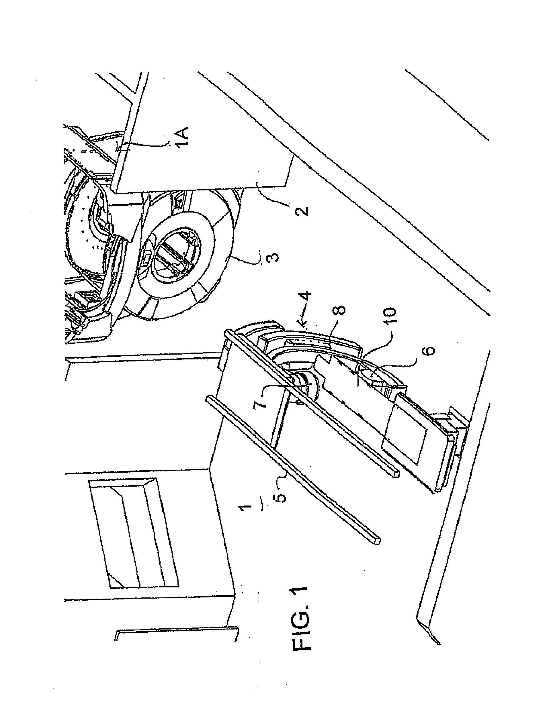
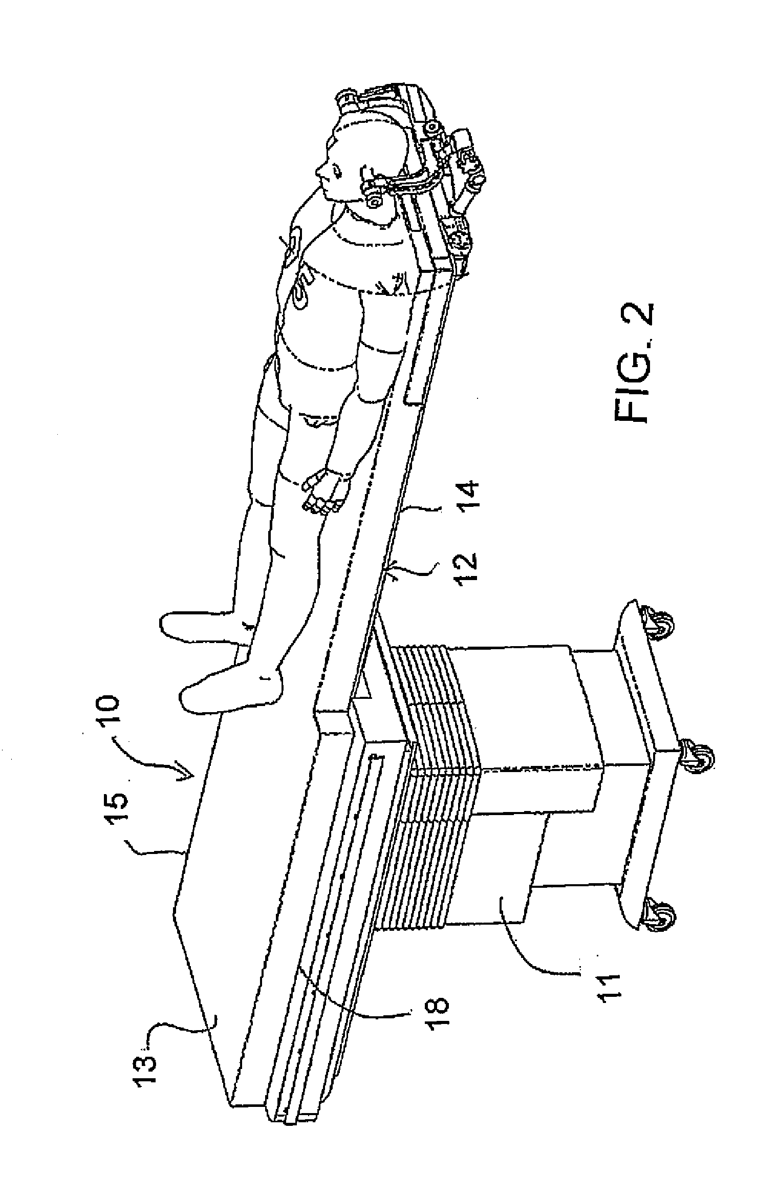
[0090]In FIG. 1 is shown an arrangement for carrying out Magnetic Resonance Imaging and X-ray imaging of a patient while the patient remains stationary on a patient support table. The arrangement provides a room 1 in which is mounted a patient support table 10 with doors 2 at one side of the room for entry into the room of the magnet 3 of an MR imaging system from a magnet bay 1A. The room contains an X-ray imaging system 4 mounted on rails 5 and includes an X-ray transmitter 6 and receiver 7 mounted on a C-shaped support 8. The X-ray system is of a conventional construction commercially available from a manufacturer such as Siemens. The table 10 described and illustrated herein is used in an arrangement where the patient remains in position on the table while imaging is effected using MRI and X-ray.

[0091]Additional unique multi-room layouts, configurations a...


PUM


Abstract

A head clamp for Magnetic Resonance and X-ray imaging is generally C-shaped including a base and two legs carrying pin clamp members. A course and fine adjustment system allows one of the clamp members to move inwardly relative to the other and then to be finely adjusted so as to apply a clamping force to the skull. The C-shaped support member comprises a truss with a C-shaped inner band adjacent the skull, an outer band generally following the shape of inner band and a plurality of openings defining spaced bars between the inner band and the outer band. The adjustment system comprises a screw that adjusts the width of the C-shaped member at the base and at one leg and includes a gauge to measure force applied with the mechanism located outside the field of view of the head both vertically and horizontally.

Description

[0001]This application claims the benefit under 35 USC 119(e) of Provisional Application 61 / 586,944 filed Jan. 16, 2012.[0002]This invention relates to a head clamp for use in imaging by magnetic resonance (MRI) and X-Ray of a patient.BACKGROUND OF THE INVENTION[0003]With MRI, a high field magnet, typically superconducting, is arranged in a torus configuration (like a donut) and with the patient lying down inside the magnet on a table where the magnetic field allows a pulsed and sequenced magnetic and EM field to probe the body to produce images, which allow the trained radiologist to determine with high probability the anatomy of the patient. MRI is sometimes performed using contrast agents introduced to the patient to provide even better contrast between different tissue types. MRI techniques are very good at detecting the anatomical location of different diseases, for example, tumours.[0004]In U.S. Pat. No. 5,735,278 (Hoult et al) issued Apr. 7, 1998, disclosed a medical procedur...

Claims


Application Information

Patent Timeline
IPC IPC(8): A61B5/055A61B6/04A61B6/00
CPCA61B19/203A61B2017/00911A61B2017/0092A61B2019/464A61B6/501A61B5/0555A61B6/0421A61B6/4417A61B6/4441A61B2019/4857A61B2090/064A61B90/14A61B2090/0811A61B5/055
Inventor MOFFATT, STEVEN
Owner DEERFIELD IMAGING INC
Learn More