
Nonlinear estimating apparatus and method and receiver

a technology of estimating apparatus and receiver, applied in the field of optical communication, can solve the problems of system becoming a problem drawing more and more attention of people, system being severely nonlinearly damaged, too complex, etc., and achieve the effect of improving the accuracy of nonlinear signal estimation

Active Publication Date: 2013-07-25
FUJITSU LTD
View PDF3 Cites 9 Cited by
  • Summary
  • Abstract
  • Description
  • Claims
  • Application Information

AI Technical Summary

Benefits of technology

The present invention provides an improved method for estimating nonlinear signals at the receiving end. This is achieved by calculating the weighted sum of interaction items of pulses on certain moments and obtaining an additive perturbation quantity and a multiplicative perturbation quantity. The accuracy of the estimation can be further improved by using these two quantities. The method is simple and applicable to different modulation formats and polarization systems.

Problems solved by technology

As the rise of transmission rate of single channel, the effect of intra-channel nonlinear originated from the present channel on the performance of a system becomes a problem drawing more and more attention of the people.
In such a case, even though the residual dispersion in the link was compensated for at the receiving side, the system would still be severely nonlinearly damaged.
However, the disadvantage of such a method is that it is too complex, and the simulation of a link configuration often needs several hours.
And at the same time, it cannot give some physically visual explanations.
However, in the implementation of the present invention, the inventors found the disadvantages of the prior art exist in: the case where both of the additive perturbation quantity and the multiplicative perturbation quantity are related to the current symbols and previous and subsequent symbols is not taken into consideration, and the accuracy of the signal estimation cannot be further improved.

Method used


Image

  • Nonlinear estimating apparatus and method and receiver
  • Nonlinear estimating apparatus and method and receiver
  • Nonlinear estimating apparatus and method and receiver

Examples


Embodiment Construction

[0039]The preferred embodiments of the present invention are described as follows in reference to the drawings. These embodiments are illustrative only, and are not intended to limit the present invention. For the easy understanding of the principles and embodiments of the present invention by those skilled in the art, the embodiments of the present invention shall be described taking an optical communication system as an example. However, it should be noted that the embodiments of the present invention are applicable to all the communication systems in which there exists nonlinear loss.

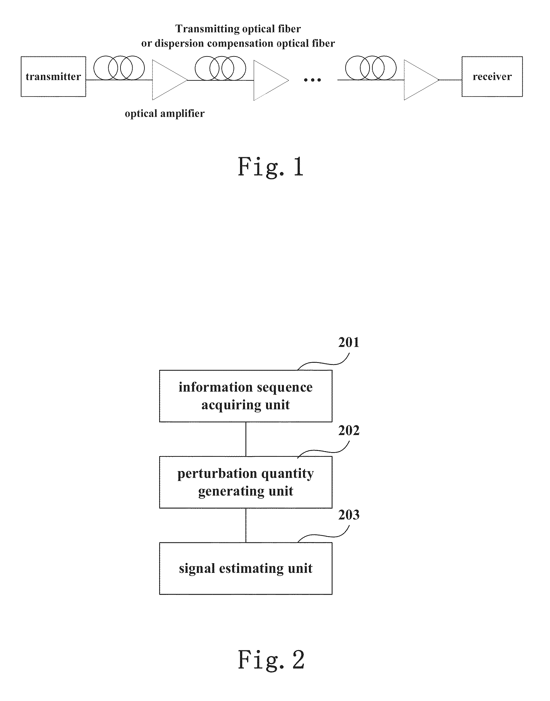
[0040]FIG. 1 is a schematic diagram of a typical optical communication system, in which the signal transmitted by a transmitter passes different devices (such as an optical fiber, an optical amplifier, and a dispersion compensation optical fiber, etc.) in a transmission link and reaches a receiver. In the embodiments of the present invention, the symbol information sequences of the inputted pulse sig...


PUM


Abstract

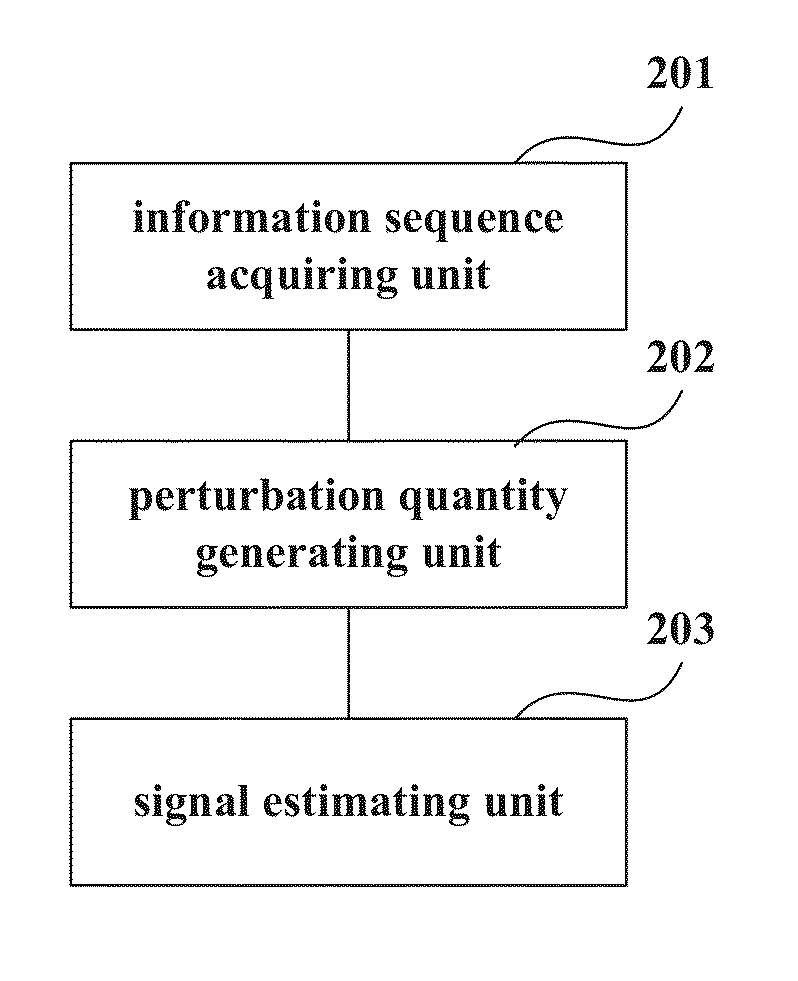
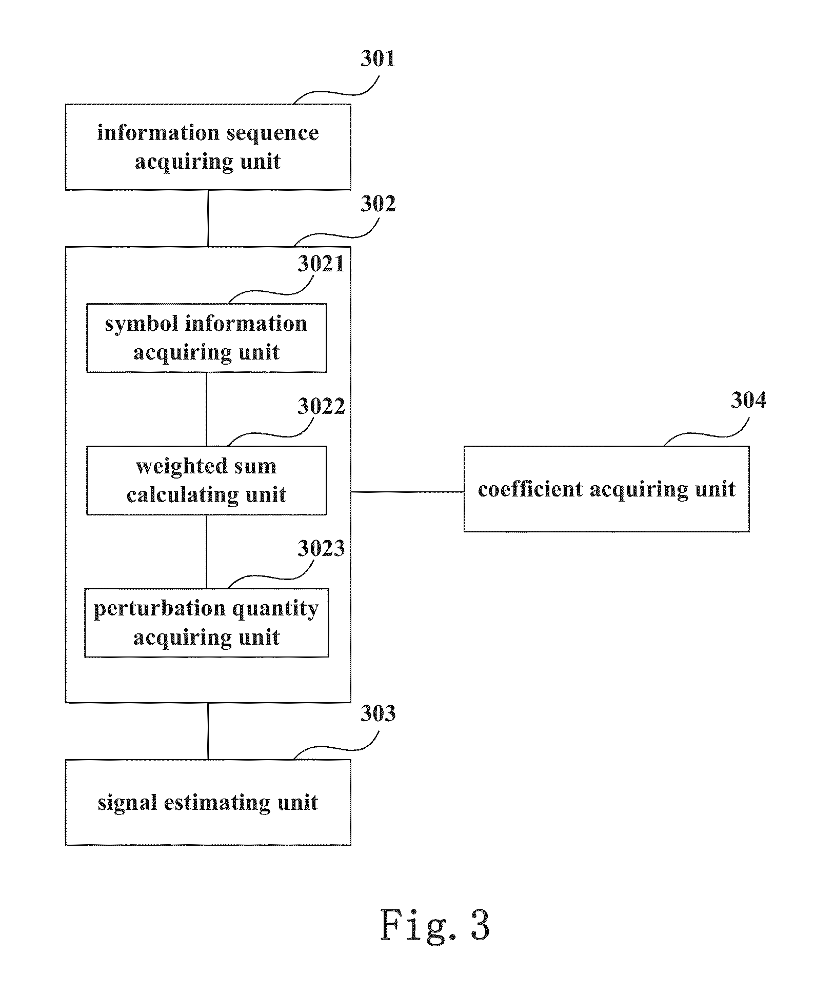
The present invention provides a nonlinear estimating apparatus and method, and a receiver. The nonlinear estimating apparatus includes: an information sequence acquiring unit, configured to acquire a symbol information sequence of the pulse signal inputted by a transmitting side; a perturbation quantity generating unit, configured to calculate the weighted sum of the interaction items of the pulses on one or more moments relative to the current moment, so as to obtain an additive perturbation quantity and a multiplicative perturbation quantity produced on a transmission link with a certain length; and a signal estimating unit, configured to estimating the signal received at a receiving side according to the symbol information sequence, the additive perturbation quantity and the multiplicative perturbation quantity. With the embodiments of the present invention, the accuracy of estimation of nonlinear signals may be further improved.

Description

TECHNICAL FIELD[0001]The present invention relates to the field of optical communication, and in particular to a nonlinear estimating apparatus and method and a receiver.BACKGROUND ART[0002]The nonlinearity in an optical fiber is originated from the Kerr effect, that is, the phase of transmitted light will be changed along with the variation of the power. Such nonlinearity is coupled with other linear effects (such as dispersion, and polarization mode dispersion, etc.), such that distortion occurs on the waveform of an optical signal at the receiver side.[0003]It is found in studies that nonlinear Schrodinger equation may well describe the coupling between such two kinds of effects in the optical fiber. For the convenience of analysis, in a wavelength division multiplexing (WDM) optical communication system, the function of the nonlinearity may be deemed as two parts by some mathematical deformation: one part is originated from interactions between a plurality of channels (different...

Claims


Application Information

Patent Timeline
Patent Type & Authority Applications(United States)
IPC IPC(8): H04B10/2543
CPCH04B10/0795H04B10/2543
Inventor DOU, LIANGTAO, ZHENNING
Owner FUJITSU LTD
Learn More