Pneumatic tire

a technology of pneumatic tires and bead parts, applied in the direction of tires, wheel components, tire beads, etc., can solve the problems of difficulty in moving a bead portion, excessive impact, and damage to the bead portion

Active Publication Date: 2013-07-25
SUMITOMO RUBBER IND LTD
View PDF10 Cites 10 Cited by
  • Summary
  • Abstract
  • Description
  • Claims
  • Application Information

AI Technical Summary

Benefits of technology

The present invention relates to a pneumatic tire with improved fitting pressure and durability. The bead cores of the tire have first and second bead wires, where the second bead wires have greater elongation than the first bead wires. The second bead wires, located in the innermost side of the tire, are designed to elongate when the bead portion moves over a hump, reducing the fitting pressure and improving the workability of mounting the tire to a rim.

Problems solved by technology

However, in a case where the tightening force of the bead core is increased, when the tire is mounted to a rim, it is difficult to move a bead portion over a hump provided in the rim, and an air pressure (hereinafter, the air pressure is referred to as “fitting pressure”) with which the tire is inflated when the bead portion is moved over the hump, is increased.
Due to the fitting pressure having been thus increased, an impact becomes excessively increased when the bead portion of the tire having been moved over the hump comes into close contact with a rim flange surface.
Therefore, the bead portion may be damaged, and durability of the bead portion may be deteriorated.

Method used


Image

  • Pneumatic tire
  • Pneumatic tire
  • Pneumatic tire

Examples


examples

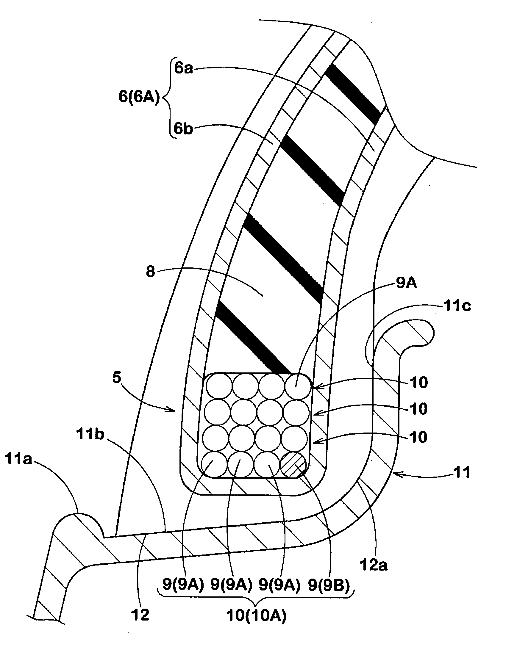
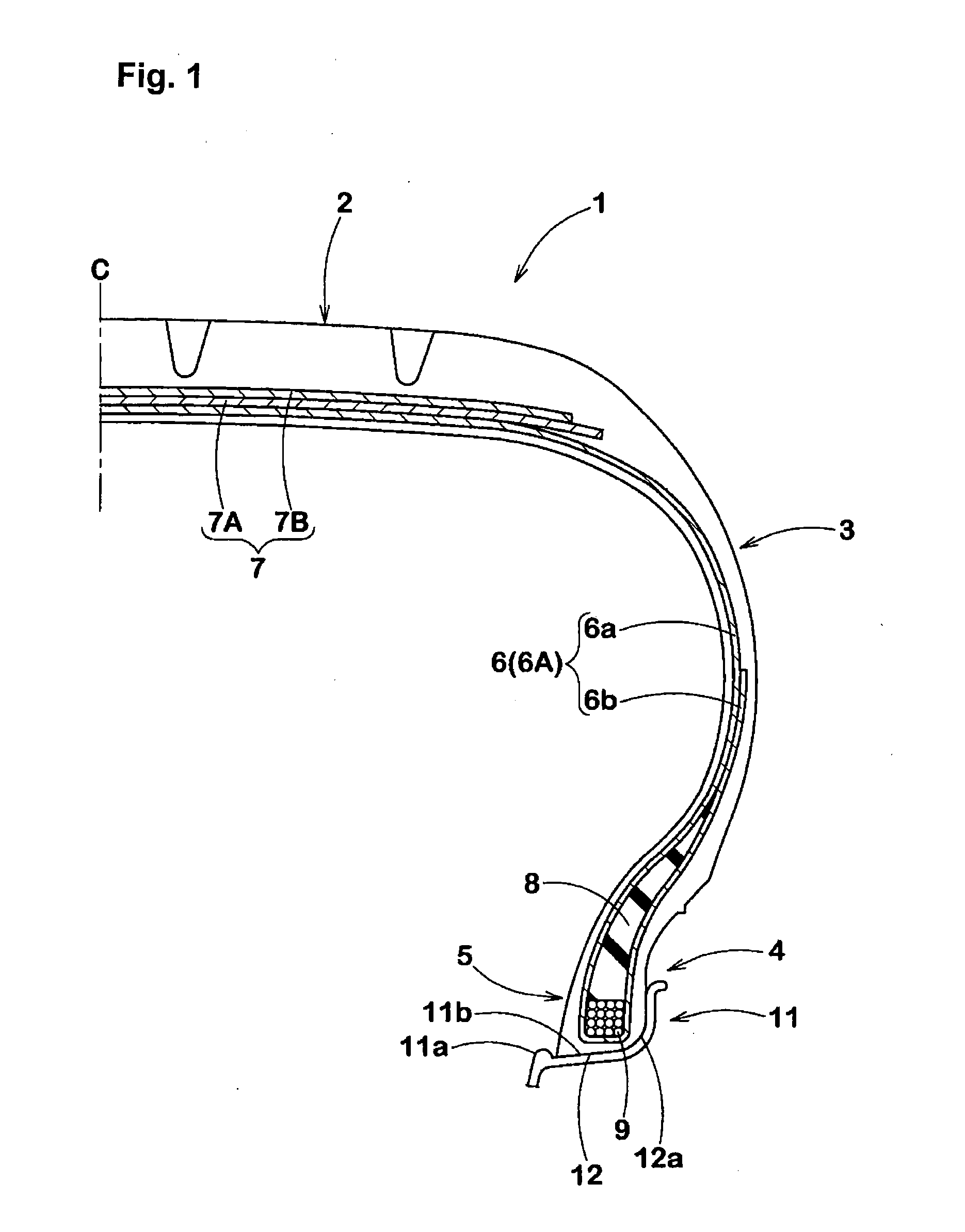
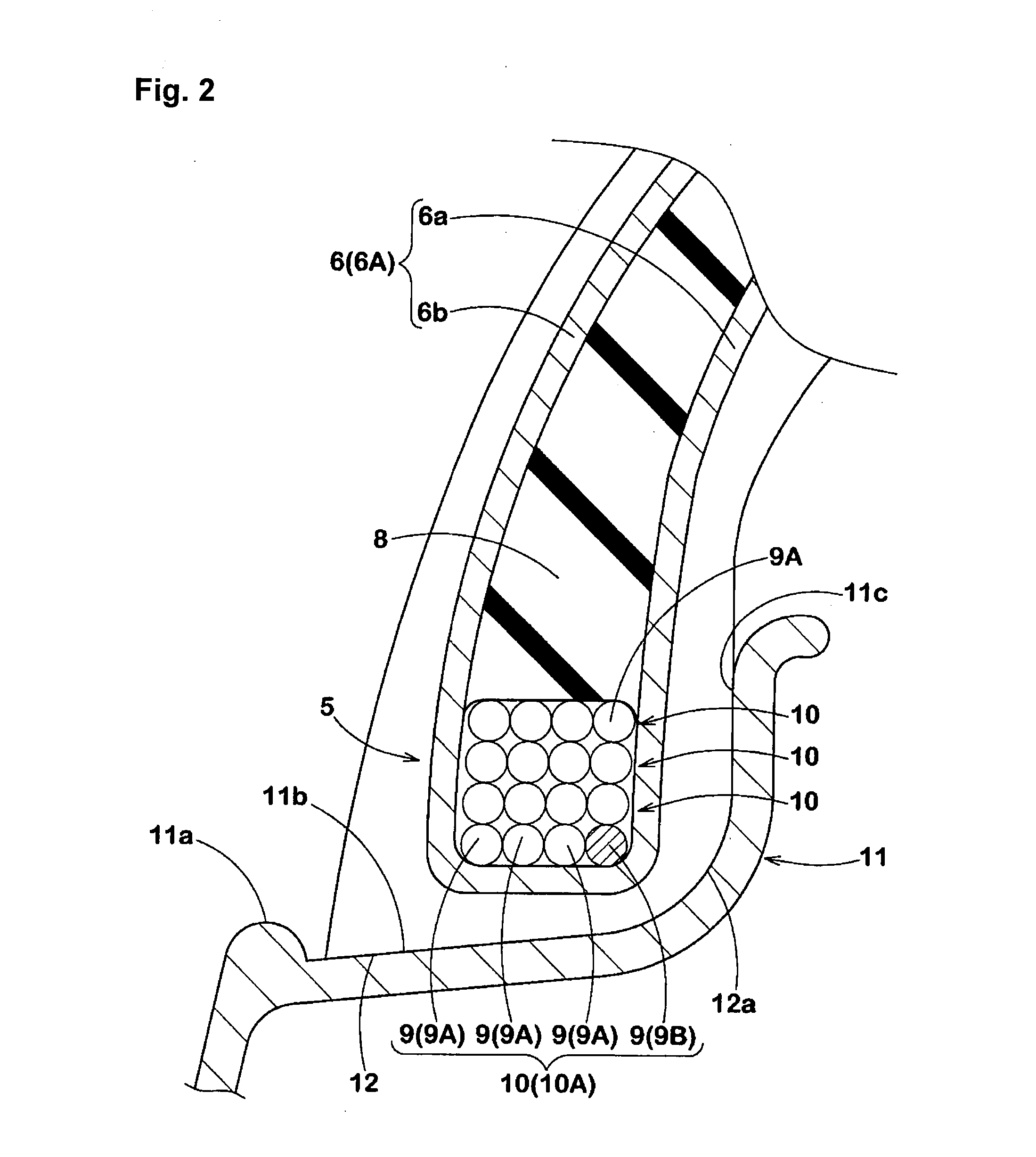
[0054]Pneumatic tires having the fundamental structure shown in FIG. 1 and having a size of 175 / 60R15 were produced based on the specifications indicated in Table 1. A rim misalignment and a fitting pressure were tested for each test tire. Further, the same test was performed, as Comparative Example, on a conventional tire in which the second bead wire was not provided. The test methods were as follows.

Rim Misalignment

[0055]Each test tire was mounted to a 15×6 JJ normal rim, and was inflated to an internal pressure of 250 kPa, and was then left indoors for 72 hours as it was. The rim having the tire mounted therein was mounted to a vehicle, and the vehicle which was running at a speed of 50 km / h was suddenly stopped once. Thereafter, a misalignment between the tire and the rim was measured. The results are indicated as indexes on the assumption that a value of an index of Comparative Example is 100. The less the value of the index is, the less the rim misalignment is.

Fitting Pressur...


PUM


Abstract

A pneumatic tire has bead cores provided in bead portions. The bead cores include a first bead wire, and a second bead wire having an elongation α, where α (%)=ΔL / L×100, L is a length of each of the bead wires under no load, and ΔL is an elongation amount obtained when a unit load is applied. The elongation α of the second bead wire is greater than an elongation of the first bead wire. The number of the second bead wire provided in an innermost side portion in a tire radial direction is at least one.

Description

CROSS-REFERENCE TO RELATED APPLICATIONS[0001]The present application is based upon and claims the benefit of priority from Japanese Application No. 2012-012320, filed Jan. 24, 2012, the entire contents of which are incorporated herein by reference.BACKGROUND OF THE INVENTION[0002]1. Field of the Invention[0003]The present invention relates to pneumatic tires that enable reduction of fitting pressure, and enhancement of workability of mounting the tires to rims and durability of bead portions while maintaining a tightening force of bead cores.[0004]2. Description of the Background Art[0005]Bead cores for use in pneumatic tires for passenger cars are each formed by one bead wire or plural bead wires being continuously wound in a tire circumferential direction. Further, various types of bead cores are suggested in order to enhance various performance characteristics of tires. For example, a bead core in which an organic fiber is used in a part of a bead wire in order to reduce a weight...

Claims


Application Information

Patent Timeline
IPC IPC(8): B60C15/04
CPCB60C15/04Y10T152/10819B60C2015/048B60C15/05
Inventor AOKI, CHIEKO
Owner SUMITOMO RUBBER IND LTD
Why Eureka
Try Eureka