Micro-valve having an elastically deformable valve lip, method for producing same and micro-pump

a micro-valve and elastically deformable technology, applied in the field of micro-valve, can solve the problems of irreparable system failure, permanent damage to the valve seat, and the need for the longest possible maintenance-free operation time, and achieve the effect of improving usability for biological applications

Inactive Publication Date: 2013-07-25
ALBERT LUDWIGS UNIV FREIBURG
View PDF8 Cites 16 Cited by
  • Summary
  • Abstract
  • Description
  • Claims
  • Application Information

AI Technical Summary

Benefits of technology

[0025]It is therefore provided in an advantageous development of the present invention, that alternatively or in addition to the elastic sealing of the first and / or second passage, at least one further elastically deformable sealing structure is arranged at the edge regions of the valve chamber and / or at the edge regions of the component towards the exterior by means of which in particular the bonding layer can be protected from the conveyed media.
[0026]According to the present invention, such a sealing seal structure is formed circumferentially, closed, flexible and deformable, and is for example made from photo-structurable silicone. Such a sealing seal structure ensures chemical resistance, for example, against etching media being transported through the micro-valve or the micro-pump and also improves usability for biological applications.

Problems solved by technology

It has been shown that with such micro-valves, the repeated impact of the diaphragm onto the comparably hard seat valve can lead to permanent damage to the valve seat.
In the course of time, this causes irreparable failure of the system due to decreasing leak tightness.
Particularly for implantable micro-systems, however, like the sphincter prosthesis, the longest possible maintenance-free operation time is essential.

Method used


Image

  • Micro-valve having an elastically deformable valve lip, method for producing same and micro-pump
  • Micro-valve having an elastically deformable valve lip, method for producing same and micro-pump
  • Micro-valve having an elastically deformable valve lip, method for producing same and micro-pump

Examples


Embodiment Construction

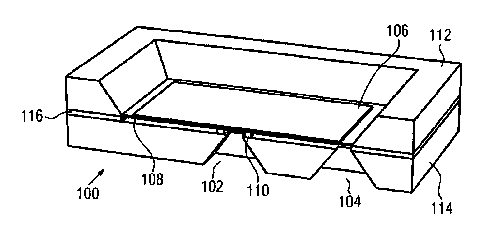
[0069]FIG. 1 shows a sectional perspective view of a micro-valve 100 according to the invention according to a first preferred embodiment. The micro-valve 100 comprises a first passage opening 102 and a second passage opening 104 through which fluid (liquid or gas) can flow in or out, respectively. It is by way of example presently assumed, that the passage 102 is an inlet and that the passage 104 is an outlet. However, other arrangements can of course be selected for the openings to be sealed. The micro-valve shown in FIG. 1 has a piezoceramic member 106 as a drive mechanism which is fixedly mounted on a diaphragm 108, for example, adhesively bonded.

[0070]In the present embodiment, the diaphragm is a silicon diaphragm 108. The diaphragm, however, can also be formed from other materials. It can be necessary to apply a conductive coating onto the diaphragm side facing the actuator side. It is also possible to apply a structured metallization on the diaphragm side, which allows the pi...


PUM

PropertyMeasurementUnit
widthsaaaaaaaaaa
tensile strengthaaaaaaaaaa

Abstract

The present invention relates to a micro-valve which is formed from two firmly connected substrates and preferably has an actuator element, for example that is diaphragm-driven, for the controlled opening and closing of a first and/or second passage. The invention further relates to a method for producing such a micro-valve and to a micro-pump which uses at least one such micro-valve. Said micro-pump is intended to be used in particular in conjunction with the development of an artificial sphincter. The micro-valve has a first substrate and a second substrate which are non-detachably joined to each other in order to form a controllable fluid flow section, and at least one first passage and at least one second passage. According to the invention, the micro-valve has at least one elastically deformable seal structure which, for example, can be formed by a photostructurable silicone, to seal off the first and/or second passage.

Description

FIELD OF THE INVENTION[0001]The present invention relates to a micro-valve which is formed from two firmly connected substrates and preferably has an actuator element, for example that is diaphragm-driven, for the controlled opening and closing of a first and / or second passage. The invention further relates to a method for producing such a micro-valve and to a micro-pump which uses at least one such micro-valve. Said micro-pump is intended to be used in particular in conjunction with the development of a hydraulic muscle (for example a sphincter) for the treatment of urinary and fecal incontinence or erectile dysfunction.BACKGROUND OF THE INVENTION[0002]During the last 20 years, a plurality of different types of micro-valves have been developed in the field of microfluidics, as is evident for example, from the review article Oh, K W et al.: “A review of micro valves”, Journal of Micromechanics and Microengineering, 16 (2006), R13-R39. Generally, micro-valves can be divided into acti...

Claims


Application Information

Patent Timeline
Patent Type & Authority Applications(United States)
IPC IPC(8): F16K27/00F17D1/00F15B13/00B21K1/20
CPCF16K99/0001F16K99/0015F16K99/0048F16K2099/0074Y10T29/49412B21K1/20F15B13/00F16K27/00F17D1/00F16K2099/0088Y10T137/85978
Inventor LEMKE, THOMASWOIAS, PETERKIOKER, JENSGOLDSCHMIDTOOING, FRANK
Owner ALBERT LUDWIGS UNIV FREIBURG
Why Eureka
Try Eureka