
Ballasted cart storage station

a cart storage and ballasted technology, applied in the direction of mechanical equipment, service system furniture, machine supports, etc., can solve the problems of preventing customers from employing, tripping hazards, and being subject to movement, so as to facilitate the maintenance of the parking area, improve the aesthetic appearance of the storage station, and minimize or prevent damage to shopping carts.

Active Publication Date: 2013-07-25
MCCUE
View PDF2 Cites 7 Cited by
  • Summary
  • Abstract
  • Description
  • Claims
  • Application Information

AI Technical Summary

Benefits of technology

The shopping cart storage station is a free-standing unit that can be relocated easily in a parking area, making maintenance and sharing with other facilities easier. The storage station is stable and prevents damage to shopping carts and cars through the use of ballast members that resemble saddles and can be engaged with the sidewalls of the storage station without the need for fasteners. The ballast members also help improve the aesthetic appearance of the parking area. Overall, the shopping cart storage station is economical, durable, and attractive to customers.

Problems solved by technology

In areas of the country where snow is common, permanently installed cart storage stations may go unplowed, preventing customers from employing them.
Since a freestanding cart storage station is not secured to the ground, it is subject to movement by shifting weather patterns or accidental collisions.
The shopping cart storage station provides a protected storage area that does not include bars or struts, which in some cases could provide a tripping hazard, extending between opposed sides of the station along the ground surface.
In addition, this feature permits shopping carts to enter the storage station in an unimpeded manner.

Method used


Image

  • Ballasted cart storage station
  • Ballasted cart storage station
  • Ballasted cart storage station

Examples


Embodiment Construction

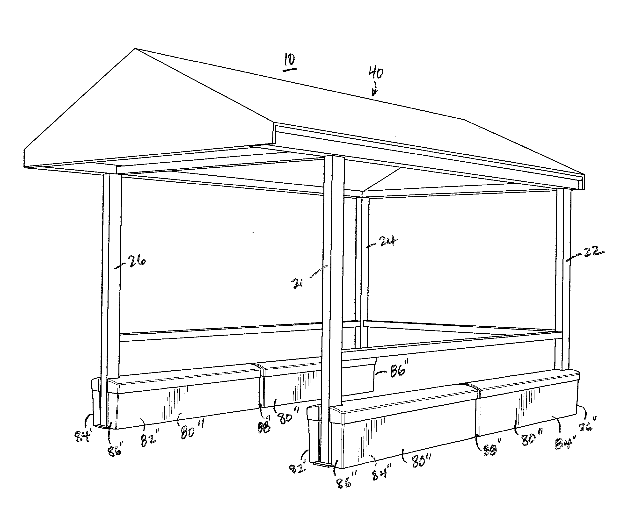
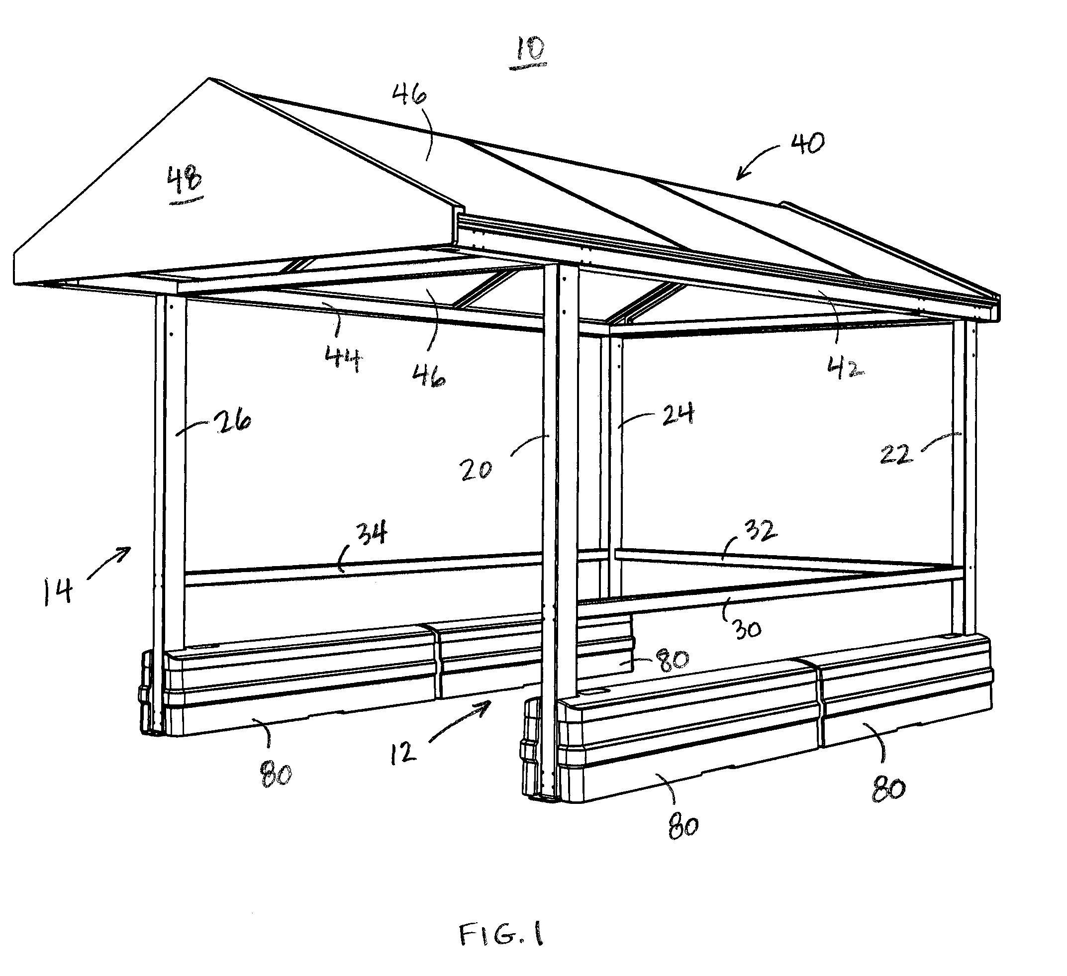
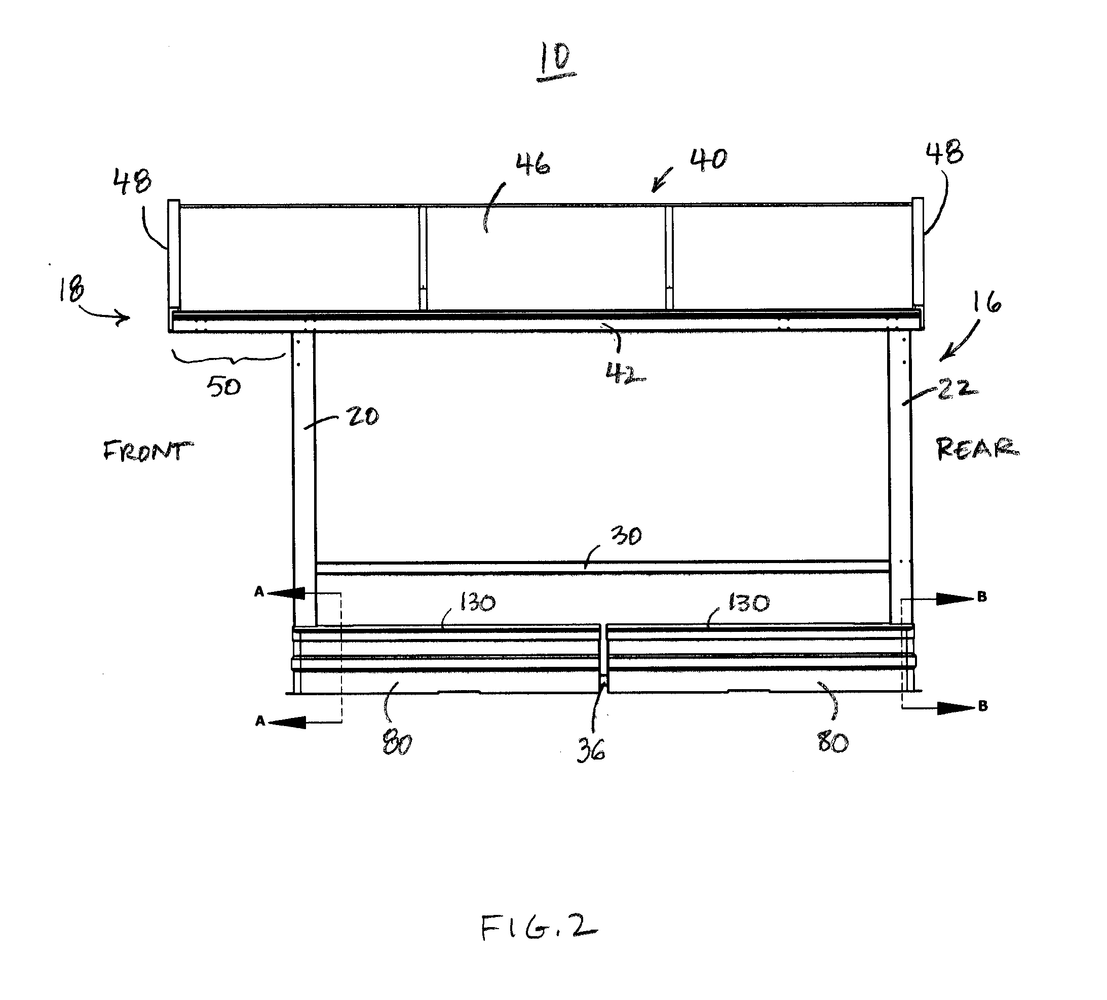
[0024]Referring now to FIGS. 1 and 2, a freestanding storage station 10 includes a pair of spaced-apart, generally parallel side members 12, 14, and a roof 40 that is supported by the side members 12, 14. The storage station 10 is stabilized relative to the ground by providing each of the side members 12, 14 with saddle-shaped ballast members 80 that engage the side members 12, 14 and rest on the ground, enabling the storage station 10 to resist movement due to weather or collision, as discussed further below.

[0025]The first side member 12 includes a first vertical support 20, and a second vertical support 22 that is spaced apart from the first vertical support 20 along the front-to-rear direction of the storage station 10. The first side member 12 further includes a horizontally-extending rail 30 that connects the first vertical support 20 to the second vertical support 22. Similarly, the second side member 14 includes a third vertical support 24, and a fourth vertical support 26 t...


PUM


Abstract

A freestanding storage station includes a pair of spaced-apart, generally parallel side members and a roof that is supported by the side members. Each side member includes a cross bar, and at least one saddle-shaped, hollow ballast-receiving member that straddles the cross bar and rests on the ground. When filled with ballast, the ballast-receiving members serve to stabilize the storage station relative to the ground and enable the storage station to resist movement due to environmental winds or collision. The ballast-receiving members include a first ballast-receiving portion and a second ballast-receiving portion, and the ballast member straddles the cross bar such that the first ballast-receiving portion resides on an interior-facing side of the cross bar and the second ballast-receiving portion resides on an exterior-facing side of the cross bar.

Description

BACKGROUND OF THE INVENTION[0001]Shopping cart storage stations are provided in the parking lots of many shopping areas, and are used to store and control shopping carts so as to avoid damage to customer's vehicles and to the shopping cans themselves, as well as to prevent clogging of parking spaces and thoroughfares. Some conventional shopping cart storage stations are permanently installed in parking lots. As used herein, the term “permanently installed” refers to being secured to the ground. Examples of being secured to the ground include being secured to the ground using a fastener, or by being partially or fully potted or embedded in the ground. In areas of the country where snow is common, permanently installed cart storage stations may go unplowed, preventing customers from employing them. For this reason, some cart storage stations are intentionally left freestanding to permit easy relocation of the station. As used herein, the term “freestanding” refers to resting on a grou...

Claims


Application Information

Patent Timeline
Patent Type & Authority Applications(United States)
IPC IPC(8): E04B1/19E04H14/00
CPCE04H6/025E04H1/1205Y10S248/91A47F10/04
Inventor MCCUE, DAVID S.HILD, BRENTMESA, TEODORO A.
Owner MCCUE
Learn More