
Finger sensor having pixel sensing circuitry for coupling electrodes and pixel sensing traces and related methods

a fingerprint sensor and circuitry technology, applied in the field of fingerprint sensors, can solve the problems of low-quality fingerprint sensors that are typically unable to capture fingerprint images, image captures that are noisy and lower quality, and the fingerprint sensor may experience problems operating in the display region, so as to reduce the noise of finger measurement

Active Publication Date: 2013-07-18
APPLE INC
View PDF3 Cites 140 Cited by
  • Summary
  • Abstract
  • Description
  • Claims
  • Application Information

AI Technical Summary

Benefits of technology

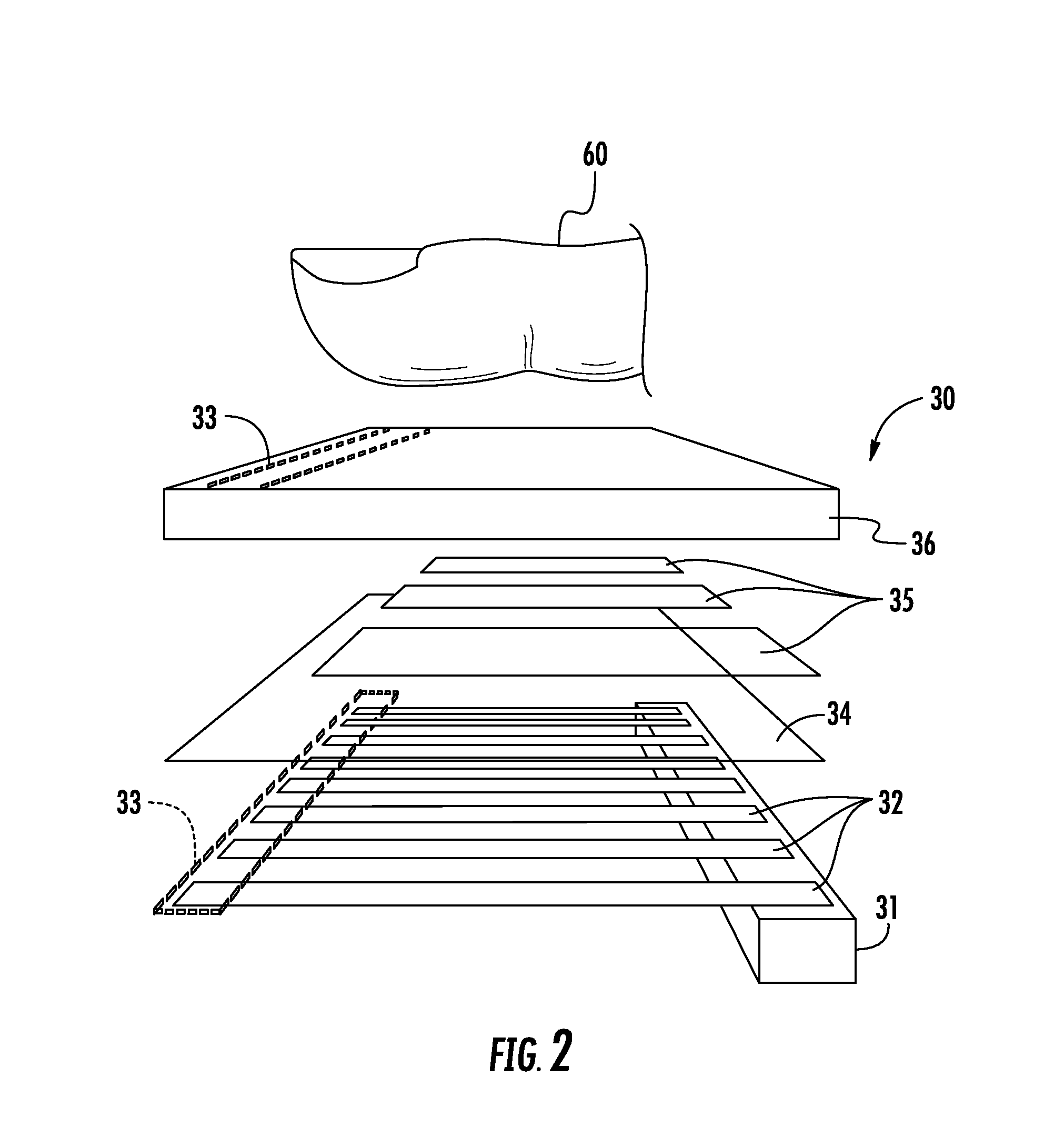
The present invention provides a finger sensor that can generate a reduced noise finger measurement from a finger, even when the finger is positioned at a relatively large distance from the finger sensing integrated circuit. This is achieved by a pixel sensing circuitry that operates in a measurement mode by coupling pixel sensing traces associated with inactive pixels to a voltage reference, while coupling electrodes associated with active pixels to a drive signal. This reduces interference from the finger and results in a more accurate finger measurement.

Problems solved by technology

In the current art, a lower quality fingerprint sensor may operate with the finger sensing area region separated from the IC, but the fingerprint sensor often may experience problems operating in the display region.
The lower quality fingerprint sensor is typically unable to capture fingerprint images through a relatively thick protective cover used over the display regions of portable electronic devices.
Thus, the images that are captured are more noisy and lower quality, which may lead to unacceptable biometric performance.

Method used


Image

  • Finger sensor having pixel sensing circuitry for coupling electrodes and pixel sensing traces and related methods
  • Finger sensor having pixel sensing circuitry for coupling electrodes and pixel sensing traces and related methods
  • Finger sensor having pixel sensing circuitry for coupling electrodes and pixel sensing traces and related methods

Examples


Embodiment Construction

[0028]The present invention will now be described more fully hereinafter with reference to the accompanying drawings, in which preferred embodiments of the invention are shown. This invention may, however, be embodied in many different forms and should not be construed as limited to the embodiments set forth herein. Rather, these embodiments are provided so that this disclosure will be thorough and complete, and will fully convey the scope of the invention to those skilled in the art. Like numbers refer to like elements throughout, and prime and multiple prime notation are used to indicate similar elements in different embodiments.

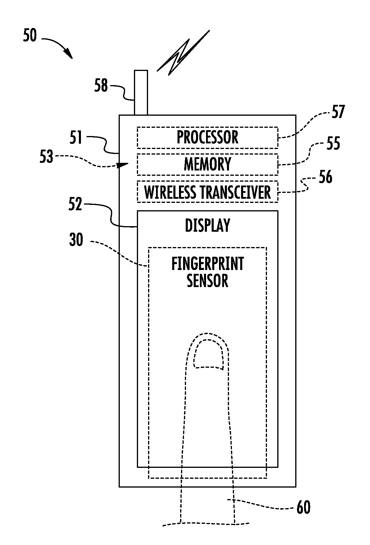
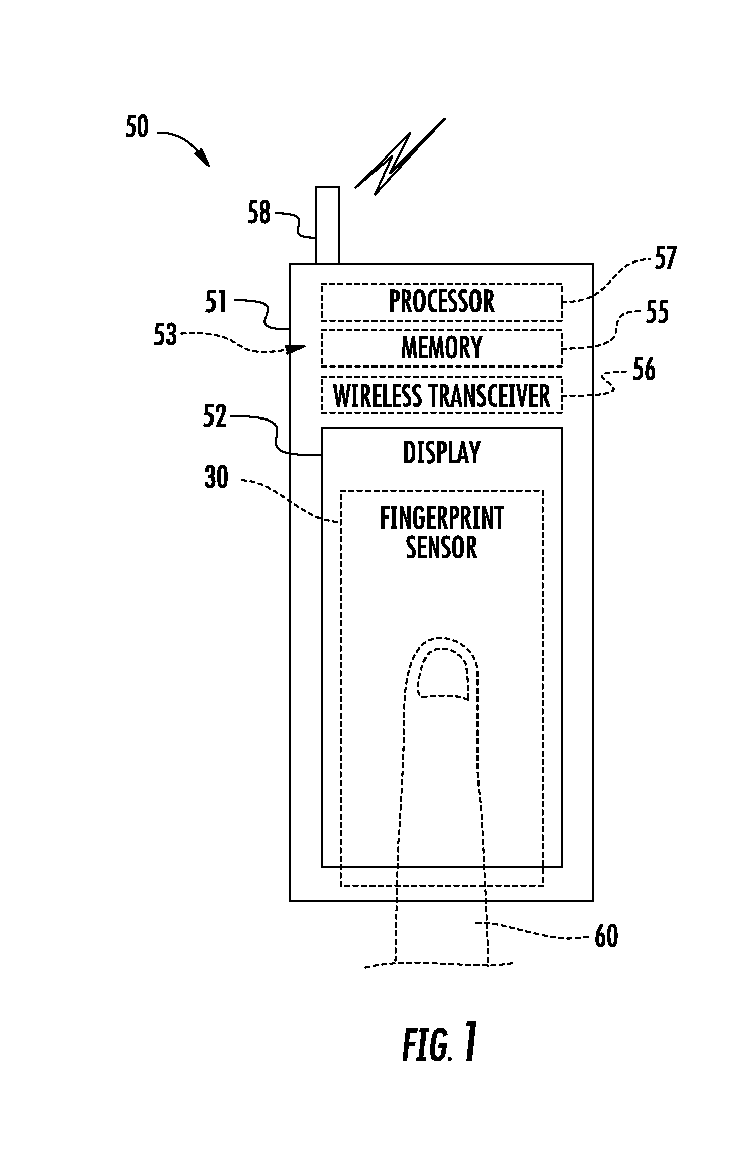
[0029]Referring initially to FIG. 1, an embodiment of a fingerprint sensor 30 in accordance with the present invention is now described. The fingerprint sensor 30 is illustratively mounted in a stacked relation with or part of a display 52. There is no array of input keys, as the display 52 is a touch-screen display so inputs are provided via the display. ...


PUM


Abstract

A finger sensor may include pixels, pixel sensing traces each associated with a respective pixel, and electrodes overlying the pixel sensing traces. The finger sensor may also include pixel sensing circuitry coupled to the pixel sensing traces and the electrodes. The pixel sensing circuitry may be capable of operating in a measurement mode by operating the pixels so that at least some of the pixels are active, and at least some other of the pixels are inactive and coupling pixel sensing traces associated with the inactive pixels to a voltage reference. The pixel sensing circuitry may also be capable of operating in the measurement mode by coupling electrodes associated with the active pixels to the voltage reference and coupling electrodes associated with the inactive pixels to a drive signal.

Description

RELATED APPLICATION[0001]The present application is based upon previously filed copending provisional application Ser. No. 61 / 587,523, filed Jan. 17, 2012, the entire subject matter of which is incorporated by reference in its entirety.FIELD OF THE INVENTION[0002]The present invention relates to the field of electronics, and, more particularly, to the field of fingerprint sensors.BACKGROUND OF THE INVENTION[0003]Fingerprint sensing and matching is a reliable and widely used technique for personal identification or verification. In particular, a common approach to fingerprint identification involves scanning a sample fingerprint or an image thereof and storing the image and / or unique characteristics of the fingerprint image. The characteristics of a sample fingerprint may be compared to information for reference fingerprints already in a database to determine proper identification of a person, such as for verification purposes.[0004]A particularly advantageous approach to fingerprint...

Claims


Application Information

Patent Timeline
IPC IPC(8): G06F3/042
CPCG06K9/0002G06F3/042G06V40/1306
Inventor SETLAK, DALE R.
Owner APPLE INC
Learn More