
Organic electroluminescent device and method for manufacturing thereof

a technology of electroluminescent devices and electroluminescent devices, which is applied in the direction of organic semiconductor devices, sustainable manufacturing/processing, and final product manufacturing, etc., can solve the problems of poor light extraction efficiency, difficulty in increasing luminance, and low refractive index of light emission, so as to simplify the manufacturing process and ensure the effect of light extraction

Inactive Publication Date: 2013-07-18
ELECTRONICS & TELECOMM RES INST
View PDF4 Cites 37 Cited by
  • Summary
  • Abstract
  • Description
  • Claims
  • Application Information

AI Technical Summary

Benefits of technology

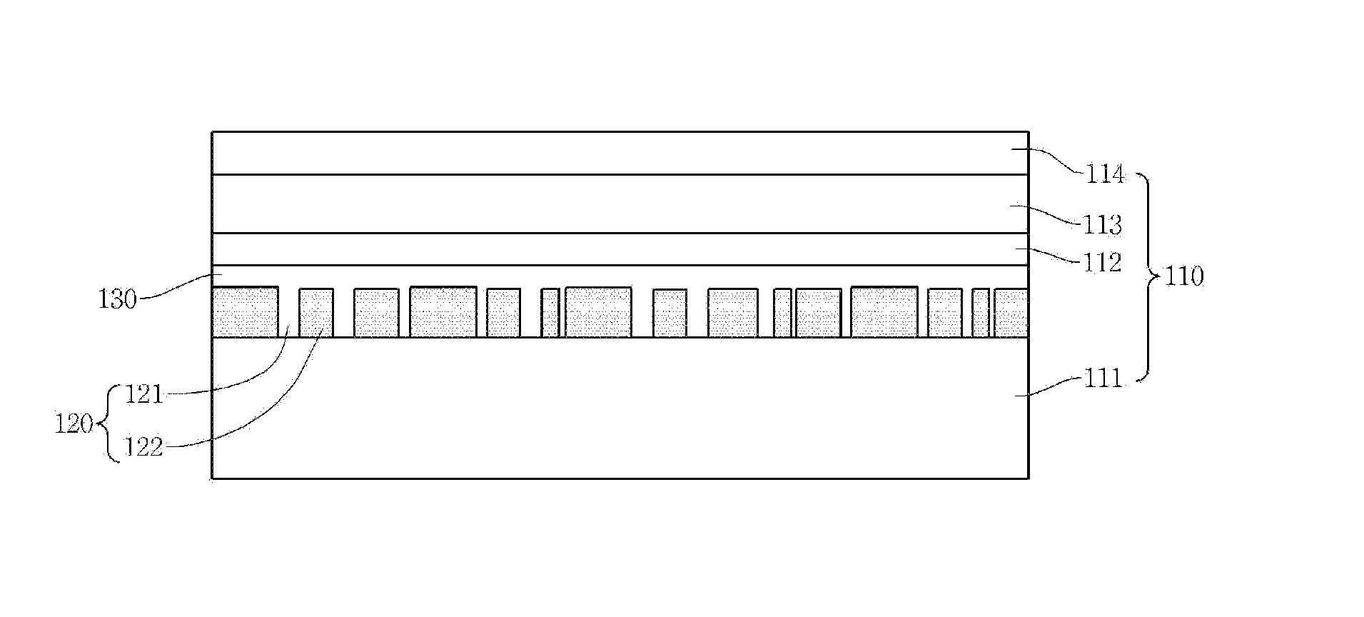
The present invention is about an organic electroluminescent device with a nano-structured surface that improves light extraction efficiency. This is achieved by randomly interposing a nano embossed structure between the substrate and the first electrode stacked on the substrate. The nano structure is generated by using dewetting phenomenon of metal, which simplifies the manufacturing process. Additionally, the refractive index, height, width gap of the nano structure can be adjusted as desired to achieve reliable light extraction, and this improves the efficiency of the organic electroluminescent device with less manufacturing cost.

Problems solved by technology

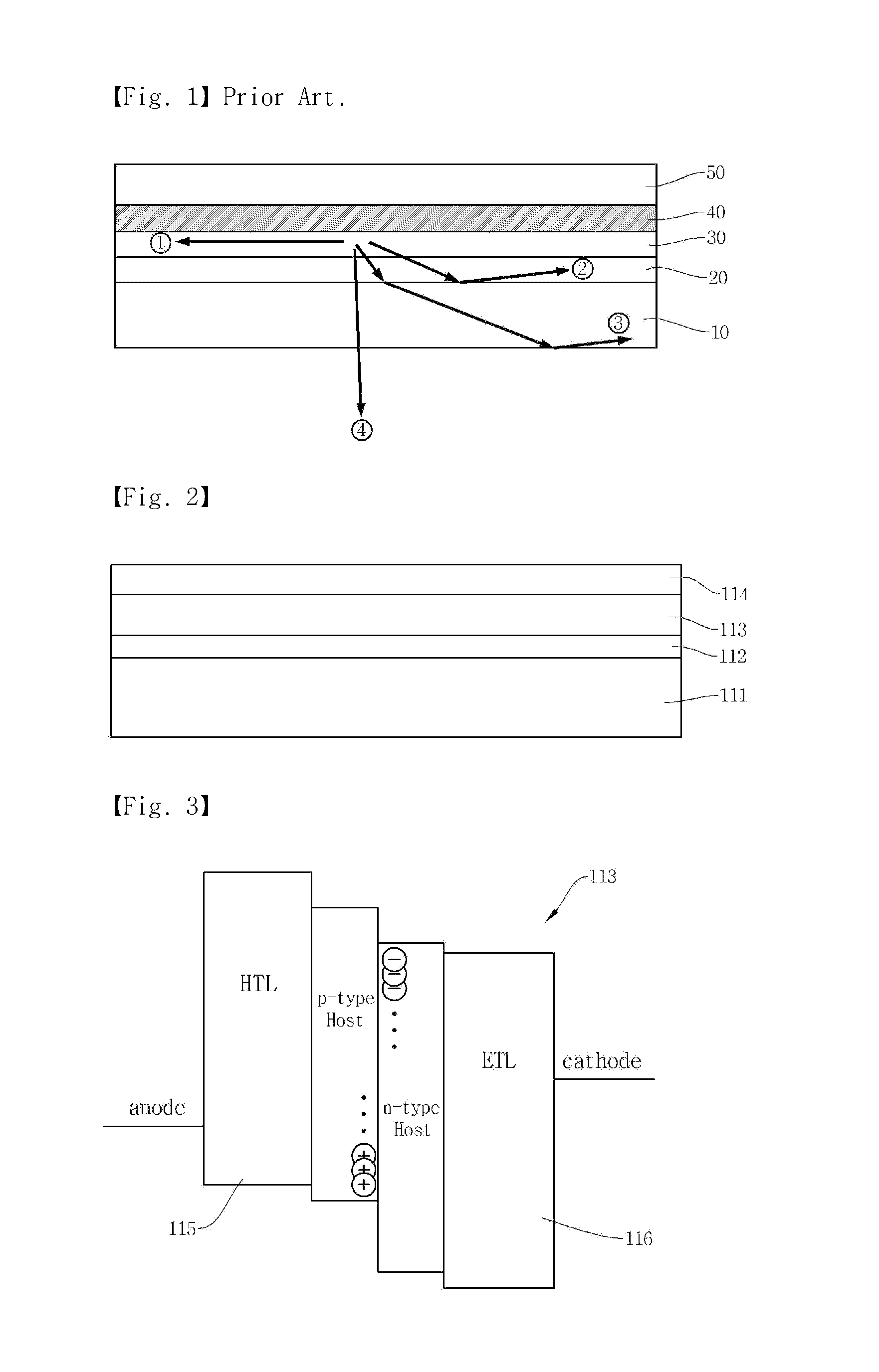
As a result, the organic electroluminescent device of prior art has a light extraction efficiency in the frontal direction of the organic display of only approximately 20%, in general, resulting in poor light extraction efficiency and difficulties in increasing luminance.
However, it is problematic that a transparent substrate, e.g., a glass substrate, used for light emission has a low refractive index of 1.5.
However, in case a refractive index of generally-used glass or plastic transparent substrate is approximately 1.5, and thickness of an organic light emitting layer in the organic electroluminescent diode and an anode layer is generally very thin, in the range of 100˜400 nm, whereby most of the light generated from the organic light emitting layer cannot be emitted to outside due to being in a guided mode.
However, because the refractive index of ITO used for anode is generally in the range of 1.9˜2.0, it is very difficult to find a material for substrate having same refractive index as that of anode.
Even if the material is available, it is very difficult to manufacture a substrate, using the material that is thin like a sheet glass, flat, smooth and in a large surface scale.

Method used


Image

  • Organic electroluminescent device and method for manufacturing thereof
  • Organic electroluminescent device and method for manufacturing thereof
  • Organic electroluminescent device and method for manufacturing thereof

Examples


Embodiment Construction

[0068]Various exemplary embodiments will be described more fully hereinafter with reference to the accompanying drawings, in which some exemplary embodiments are shown. The present inventive concept may, however, be embodied in many different forms and should not be construed as limited to the example embodiments set forth herein. Rather, these exemplary embodiments are provided so that this description will be thorough and complete, and will fully convey the scope of the present inventive concept to those skilled in the art.

[0069]Unless otherwise defined, all terms (including technical and scientific terms) used herein have the same meaning as commonly understood by one of ordinary skill in the art to which this inventive concept belongs. It will be further understood that terms, such as those defined in commonly used dictionaries, should be interpreted as having a meaning that is consistent with their meaning in the context of the relevant art and will not be interpreted in an ide...


PUM


Abstract

Disclosed is an organic electroluminescent device and a method for manufacturing thereof, the device including a light emitting part in which a substrate, a first electrode, an organic light emitting layer and a second electrode, and a nano structure including a first opening part randomly distributed between the substrate and the first electrode, wherein the nano structure includes at least anyone of polyimide, epoxy, polycarbonate, PVC, PVP, polyethylene, polyacryl and perylene, each having a refractive index in the range of 1.3˜1.5, whereby a light extraction can be improved by restricting a reflective light from an interface between the substrate and the first electrode.

Description

[0001]Pursuant to 35 U.S.C. §119 (a), this application claims the benefit of earlier filing date and right of priority to Korean Patent Application No. 10-2012-0005744, filed on Jan. 18, 2012, the contents of which is hereby incorporated by reference in their entirety.BACKGROUND OF THE DISCLOSURE[0002]1. Field[0003]The teachings in accordance with the exemplary embodiments of this present disclosure generally relate to an organic electroluminescent device and a method for manufacturing thereof, and more particularly to an organic electroluminescent device including a nano embossing structure configured to induce a light extraction of an organic electroluminescent device, and a method for manufacturing thereof.[0004]2. Background[0005]Organic electroluminescent devices, for example, organic electroluminescent diodes, are provided with a thin film containing a light-emitting organic compound between an anode and a cathode. By injecting holes and electrons from the respective electrode...

Claims


Application Information

Patent Timeline
IPC IPC(8): H01L51/52H01L51/56B82Y99/00
CPCH01L51/0096H01L51/5268B82Y20/00Y02E10/549H01L2251/105Y02P70/50H10K77/10H10K71/821H10K50/854H10K50/86H05B33/10H05B33/22
Inventor CHO, DOO-HEE
Owner ELECTRONICS & TELECOMM RES INST
Learn More