Eureka AIR delivers breakthrough ideas for toughest innovation challenges, trusted by R&D personnel around the world.

Method and Apparatus for Detecting Secondary Synchronization Signal

a synchronization signal and secondary synchronization technology, applied in the field of radio communication, can solve the problems of increasing the computational complexity the detection has a very high computational complexity, and the detection performance is more affected, so as to reduce the calculation quantity of the correlation calculation, increase the additional resource consumption, and improve the detection efficiency

Active Publication Date: 2013-07-11
SANECHIPS TECH CO LTD
View PDF2 Cites 53 Cited by
  • Summary
  • Abstract
  • Description
  • Claims
  • Application Information

AI Technical Summary

Benefits of technology

The present invention provides a method and apparatus for detecting a secondary synchronization signal. The method and apparatus use the two round detection method to reduce computational complexity and ensure performance. Additionally, a threshold denoising method is used for channel estimation to improve performance. The detection process involves multiple times of FFT / IFFT and a high efficient scheduling policy to occupy the least resources. Overall, the present invention achieves efficient and reliable detection of the secondary synchronization signal.

Problems solved by technology

This method uses a method for noncoherent detection, and comparing with the coherent detection, its detection performance has greater degradation, and its correlation calculation uses the total sequence detection, which has the very high computational complexity.
With this method, the computational complexity of the correlation calculation is more greatly reduced, however, the implementation process introduces more address mapping and de-mapping, which additionally increases the resource consumption.

Method used


Image

  • Method and Apparatus for Detecting Secondary Synchronization Signal
  • Method and Apparatus for Detecting Secondary Synchronization Signal
  • Method and Apparatus for Detecting Secondary Synchronization Signal

Examples


example

[0179]As shown in FIG. 14, the specific flow for detecting the secondary synchronization signal by using the scheme of the present invention is as follows:

[0180]S1, the PSS position of the first correlation peak value in the PSS detection table and the corresponding frame structure type are obtained;

[0181]herein the first correlation peak value is obtained by the PSS detection using to number the peak value from the large to the small, namely the maximum peak value.

[0182]S2, the possible SSS range is deduced by the PSS position according to the frame structure type and the CP mode, and SSS symbols and PSS symbols in two modes of the extended CP and the normal CP after performing the frequency offset compensation are buffered;

[0183]as for the FDD frame structure type, the SSS symbols and the PSS symbols use the continuous storage way; whereas as for the TDD frame structure type, the SSS coverage data range and the PSS symbols in two CP modes are divided into two segments to be stored...


PUM


Abstract

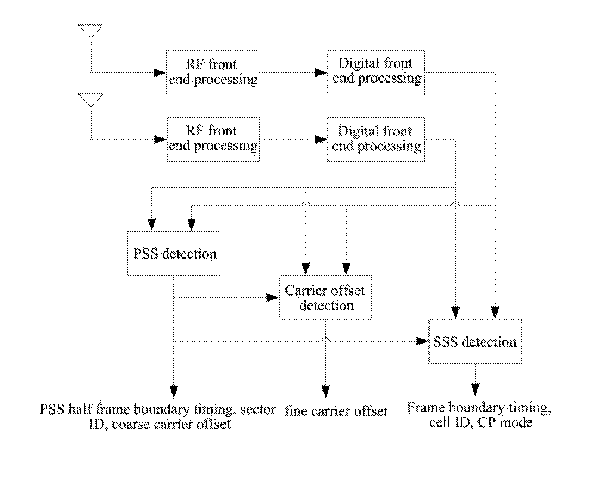
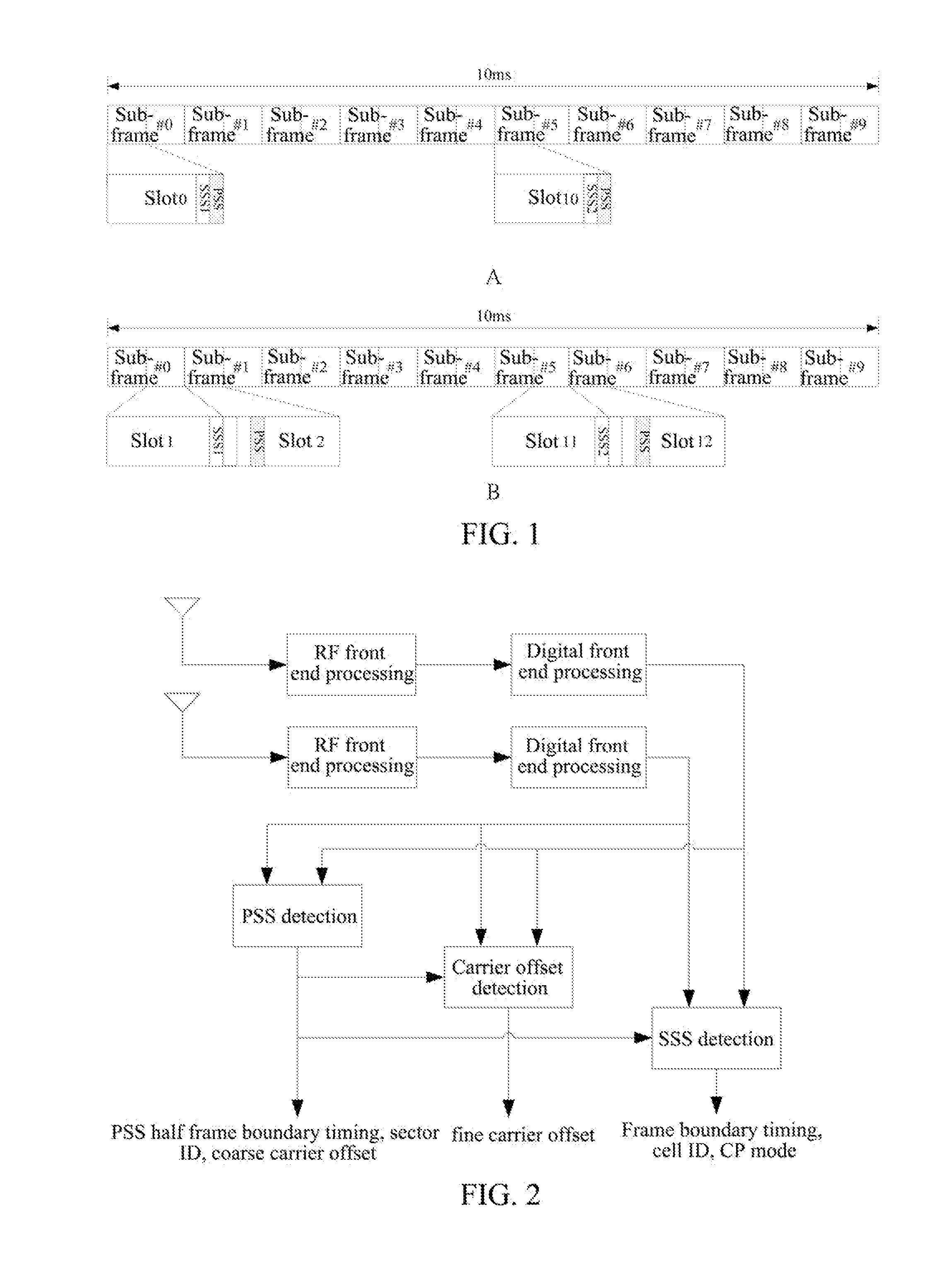
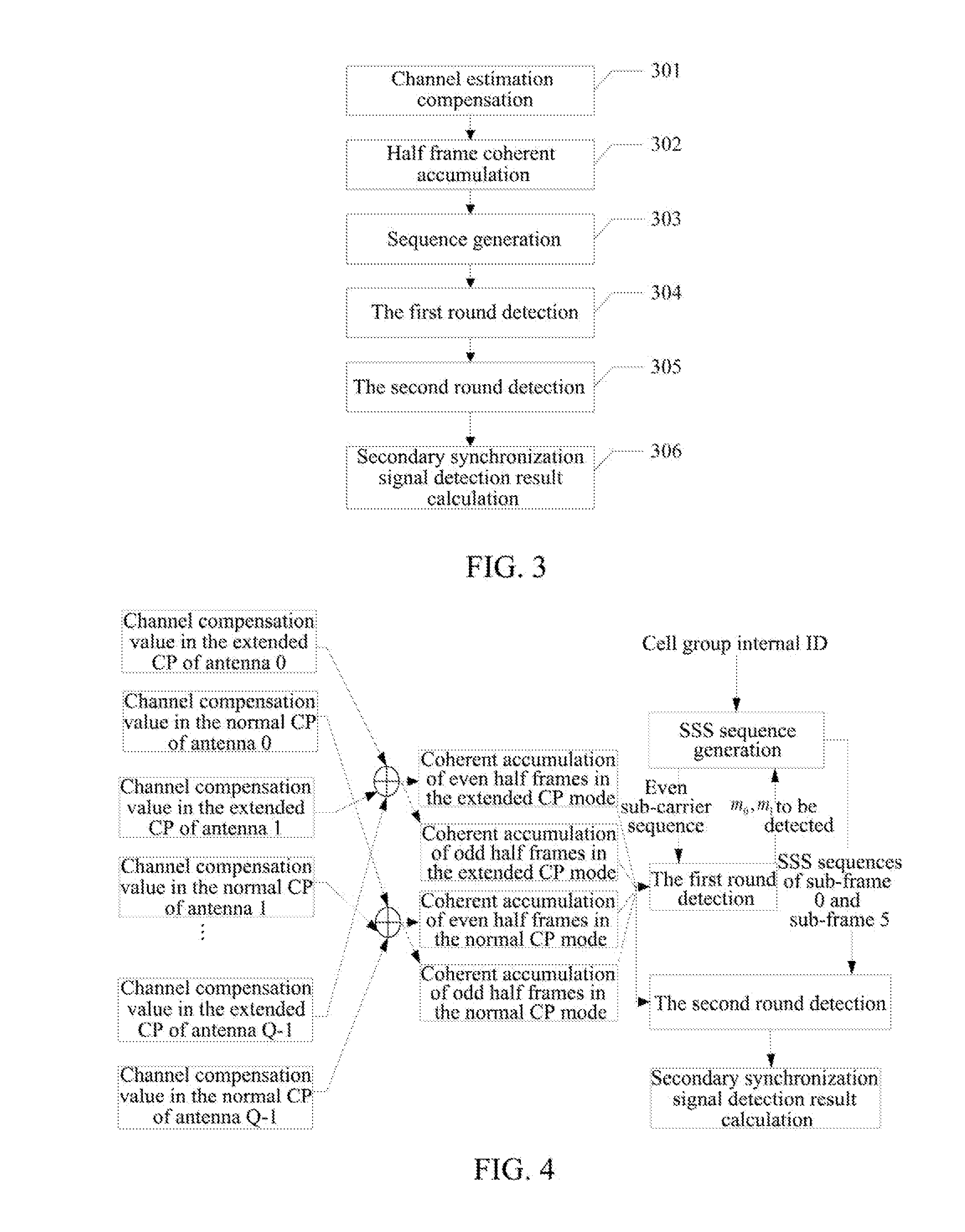
a method and apparatus for detecting a secondary synchronization signal, the method including: calculating a channel estimation compensation value of each sub-carrier of a Secondary Synchronization Signal (SSS) symbol in different Cyclic Prefix (CP) modes; obtaining coherent accumulative results of even half frames and odd half frames of each sub-carrier according to the channel estimation compensation value of each sub-carrier of said SSS symbol; generating a SSS sequence; obtaining an index of the SSS sequence corresponding to an over-threshold value of a first round detection, determining indexes composed of the SSS sequence used in a second round detection according to said index, using coherent accumulative results of all the sub-carriers in the even and odd half frames and SSS sequences of all the sub-carriers to obtain an over-threshold value of the second round detection; and obtaining a CP mode, and calculating a cell ID and a radio frame boundary.

Description

TECHNICAL FIELD[0001]The present invention relates to the radio communication field, and in particular, to a method and an apparatus for detecting a secondary synchronization signal.BACKGROUND OF THE RELATED ART[0002]In order to satisfy the increasing requirements for the data services of people's, the 3rd Generation Partnership Project (3GPP) starts the Long Term Evolution (LTE) project of the 3G system, which aims at providing stronger data service support and providing better services for users by the successively evolved 3G systems. The LTE system adopts the Orthogonal Frequency Division Multiplexing (OFDM) transmission technique, which improves the spectrum efficiency and the robustness of the system to the frequency selective channel.[0003]In the radio communication system, when the UE is just powered on, is idle and is in the activated state, the UE is required to perform the cell search to obtain more detailed information about the cell and adjacent cells, so as to initiate ...

Claims


Application Information

Patent Timeline
IPC IPC(8): H04W56/00
CPCH04J11/0076H04L27/2656H04L27/2672H04W56/00H04L27/2684H04L27/2695H04L27/2675
Inventor YI, LIQIANG
Owner SANECHIPS TECH CO LTD
Why Eureka
Eureka Blog
Learn More