
Pole-slip protection system and method for synchronous machines

a protection system and synchronous machine technology, applied in the direction of electric motor control, generator circuit arrangement control, electric generator control, etc., can solve problems such as unstable machine arrangemen

Active Publication Date: 2013-07-11
NORTH WEST UNIV (ZA)
View PDF5 Cites 12 Cited by
  • Summary
  • Abstract
  • Description
  • Claims
  • Application Information

AI Technical Summary

Benefits of technology

The present invention provides a method for protecting a synchronous machine arrangement connected to an electricity network against pole-slip. The method involves continuously monitoring a first variable parameter, deriving a representation of a second parameter based on data from a third parameter before the fault, and utilizing the representation and a stability criterion to predict whether the machine arrangement may become unstable. If instability is predicted, the machine arrangement is disconnected from the network before or after the fault is cleared. The method may be implemented using a controller or computer program. The technical effect of the invention is to provide a reliable and effective method for protecting synchronous machines against pole-slip, which can prevent damage and reduce downtime.

Problems solved by technology

Hence, the machine arrangement is disconnected from the network before the machine arrangement becomes unstable.

Method used


Image

  • Pole-slip protection system and method for synchronous machines
  • Pole-slip protection system and method for synchronous machines
  • Pole-slip protection system and method for synchronous machines

Examples


Embodiment Construction

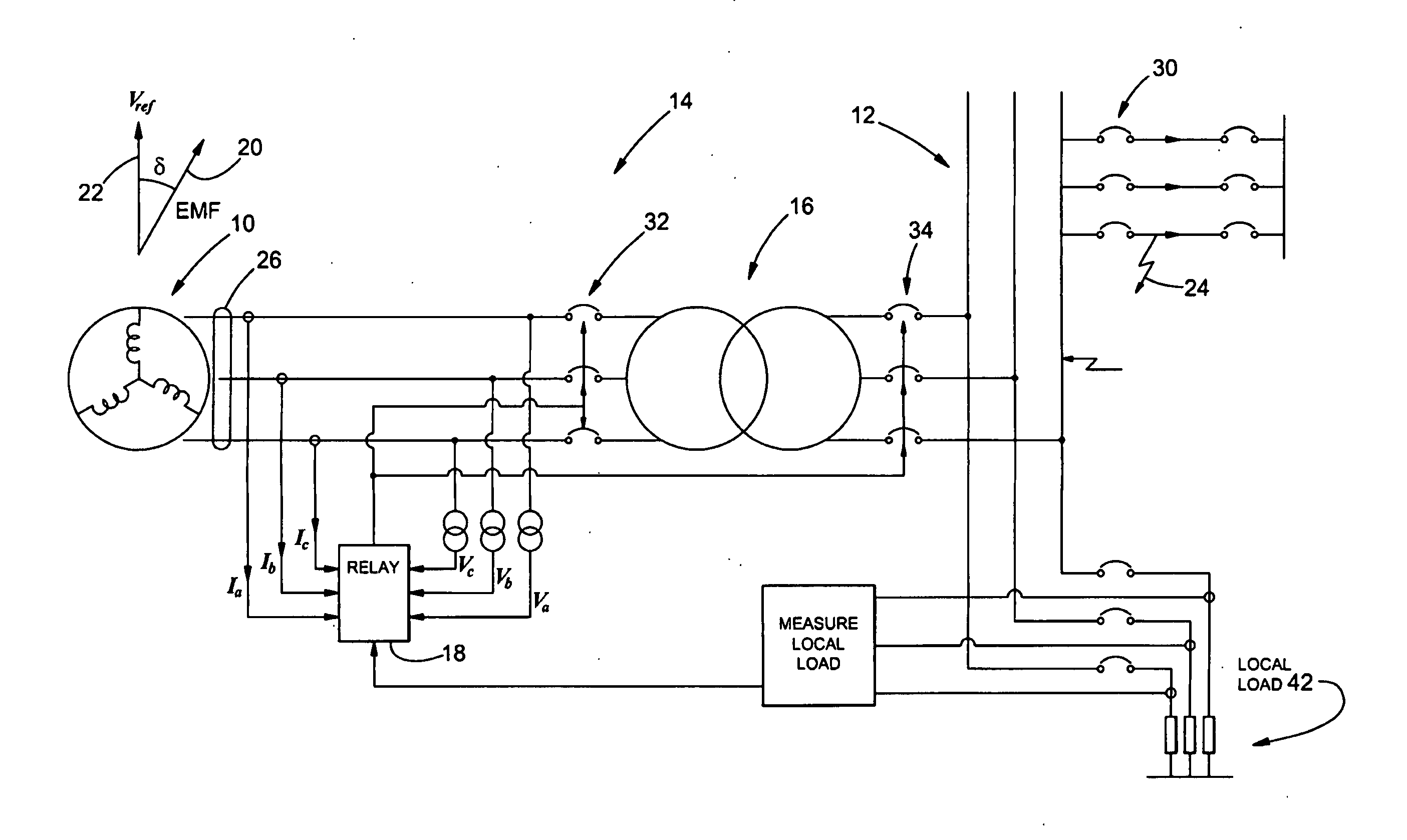
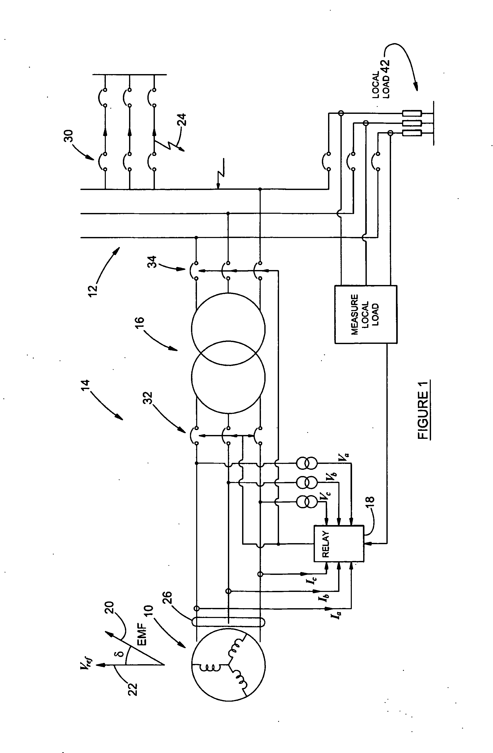
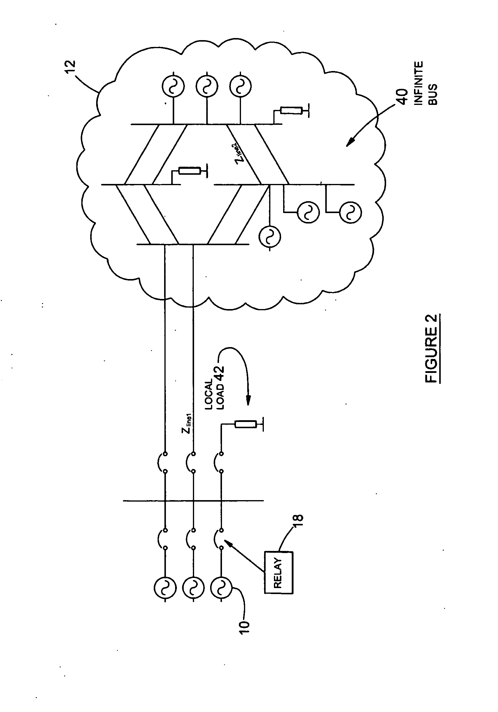
[0047]Referring to FIGS. 1 and 2, there is shown a synchronous rotating machine in the form of a power generator 10 connected to an electricity network 12. The machine 10 forms part of a machine arrangement 14 also comprising an associated transformer 16.

[0048]A computerized protection relay 18 comprises a controller comprising a processor and an associated memory arrangement. The processor is configured to execute a pole-slip detection and protection application program comprising a program code for performing a method of protecting the synchronous machine arrangement against pole-slip as will hereinafter be described.

[0049]The method comprises the steps of the relay 18 continuously computing and monitoring a first variable parameter relating to the machine arrangement with reference to a reference value. In this example embodiment, the first parameter is a power transfer angle (δ) between an electromotive force (EMF) 20 of the machine 10 and a reference voltage (Vref) 22. In the e...


PUM


Abstract

A method of protecting a synchronous machine (10) connected to an electricity network (12) against pole-slip comprises the steps of continuously monitoring a power transfer angle (δ) between an electromotive force (EMF) of the machine and a reference voltage Vref. In the event of a fault (24) on the electricity network which may result in pole-slip of the machine (10), deriving a representation of power transfer (P) relating to the machine against the power transfer angle (δ) utilizing data relating to a value of a current or a voltage measured on a terminal (26) of the machine before the fault has occurred and computed data relating to an expected future value of a current or voltage on the terminal (26), after the fault has occurred. The method then utilizes the representation and a stability criterion to predict whether the machine (10) may become unstable and if instability is predicted, causes the machine (10) to be disconnected at 32 or 34 from the electricity network (12).

Description

INTRODUCTION AND BACKGROUND[0001]This invention relates to protection systems and methods for synchronous machines and more particularly to a method of protecting a synchronous machine arrangement connected to an electricity network against pole-slip and a pole-slip protection relay.[0002]Pole-slipping in synchronous machines occurs when there is insufficient electromagnetic torque to hold the rotor in synchronism with the stator magnetic flux. Typically, pole-slipping occurs under severe fault conditions that cause a transient torque which exceeds the ability of the rotor magnetic field to keep the rotor synchronized with the stator rotating magnetic field. Synchronous generators may pole-slip due to faults in the network, power swings and loss-of-excitation. Synchronous motors may pole-slip during under-voltage conditions, loss of excitation and during sudden mechanical failure.[0003]For example, in the case of a generator connected to a network and driven by a prime-mover in the ...

Claims


Application Information

Patent Timeline
IPC IPC(8): H02H3/48
CPCH02P9/009H02P9/10H02H3/48H02P25/023H02P29/02H02P9/302H02P25/03H02H1/04H02H7/0805
Inventor DE KOCK, JAN ABRAHAMLAMONT, LAFRAS
Owner NORTH WEST UNIV (ZA)
Learn More