
Gripper assembly for a manipulator and method of use

a technology of manipulator and assembly, which is applied in the direction of forging/hammering/hammering machines, handling devices, forging/hammering/hammering apparatus, etc., can solve the problems of uneven temperature profile of metal ingots, inability to achieve heat transfer, and irregularities in the physical characteristics of forged parts, so as to prevent heat transfer

Inactive Publication Date: 2013-07-11
FIRTH RIXSON
View PDF0 Cites 10 Cited by
  • Summary
  • Abstract
  • Description
  • Claims
  • Application Information

AI Technical Summary

Benefits of technology

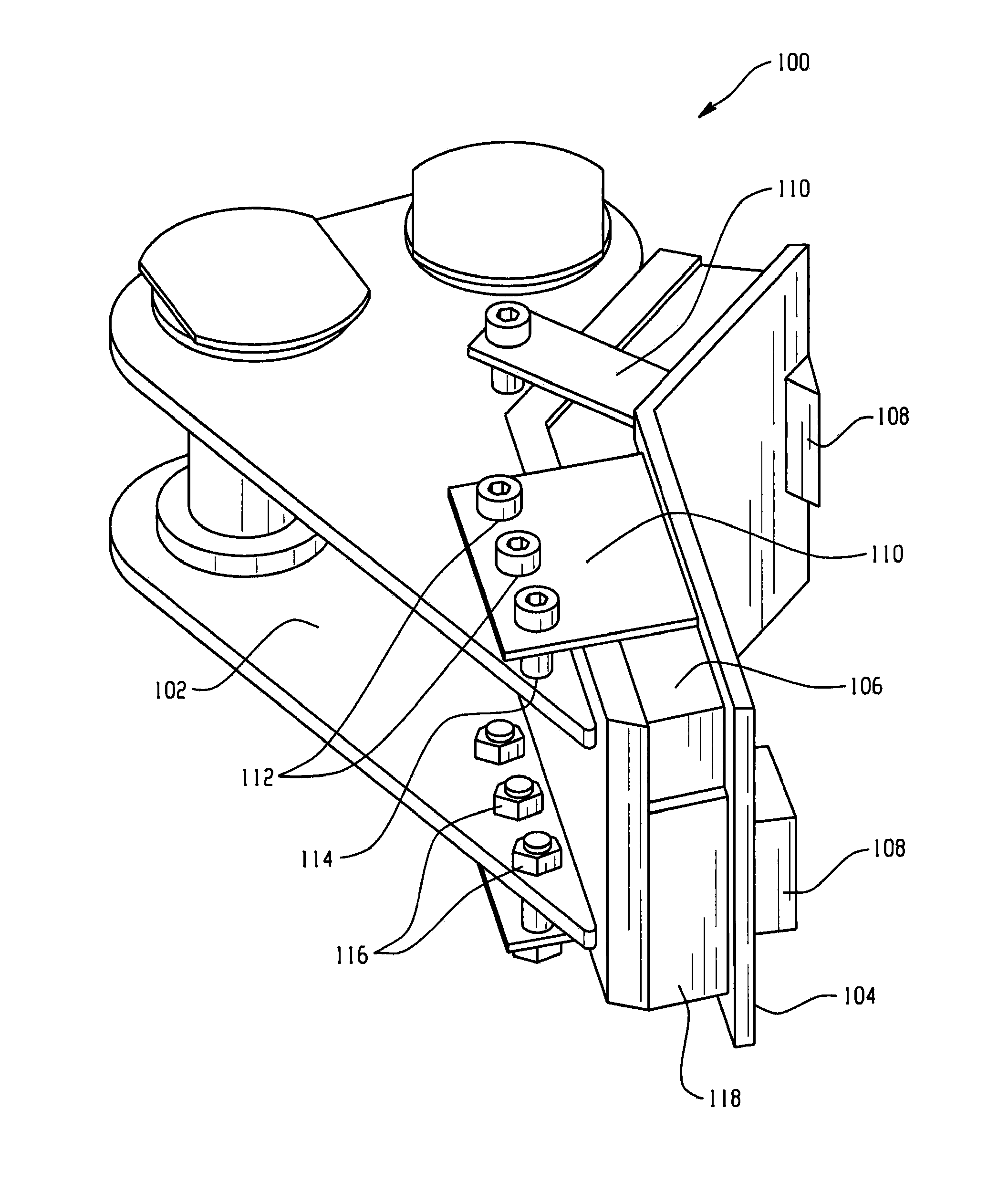
The patent is about systems and methods for handling heated metal parts during forging processes. The technical effect of this patent is the use of grieler assemblies with insulating plates to prevent heat transfer from the metal part to the main body and allow for safe handling and movement of the metal part during the forging process.

Problems solved by technology

Transfer of heat from the metal ingot is undesirable, because the metal needs to be kept at a certain, uniform temperature in order for proper formation of the part into the desired shape in the forging process.
When heat is lost from those portions of the ingot in contact with the manipulator, the metal ingot will have an uneven temperature profile.
The differences in temperature throughout the metal ingot can cause problems (e.g., irregularities) in the physical characteristics of the forged part.
This problem can be particularly acute in the forging of smaller parts that will lose heat more quickly than large pieces of metal.
Moreover, repeated cycles of heating and cooling the gripper assemblies and manipulator arms can degrade components over time.

Method used


Image

  • Gripper assembly for a manipulator and method of use
  • Gripper assembly for a manipulator and method of use
  • Gripper assembly for a manipulator and method of use

Examples


example 1

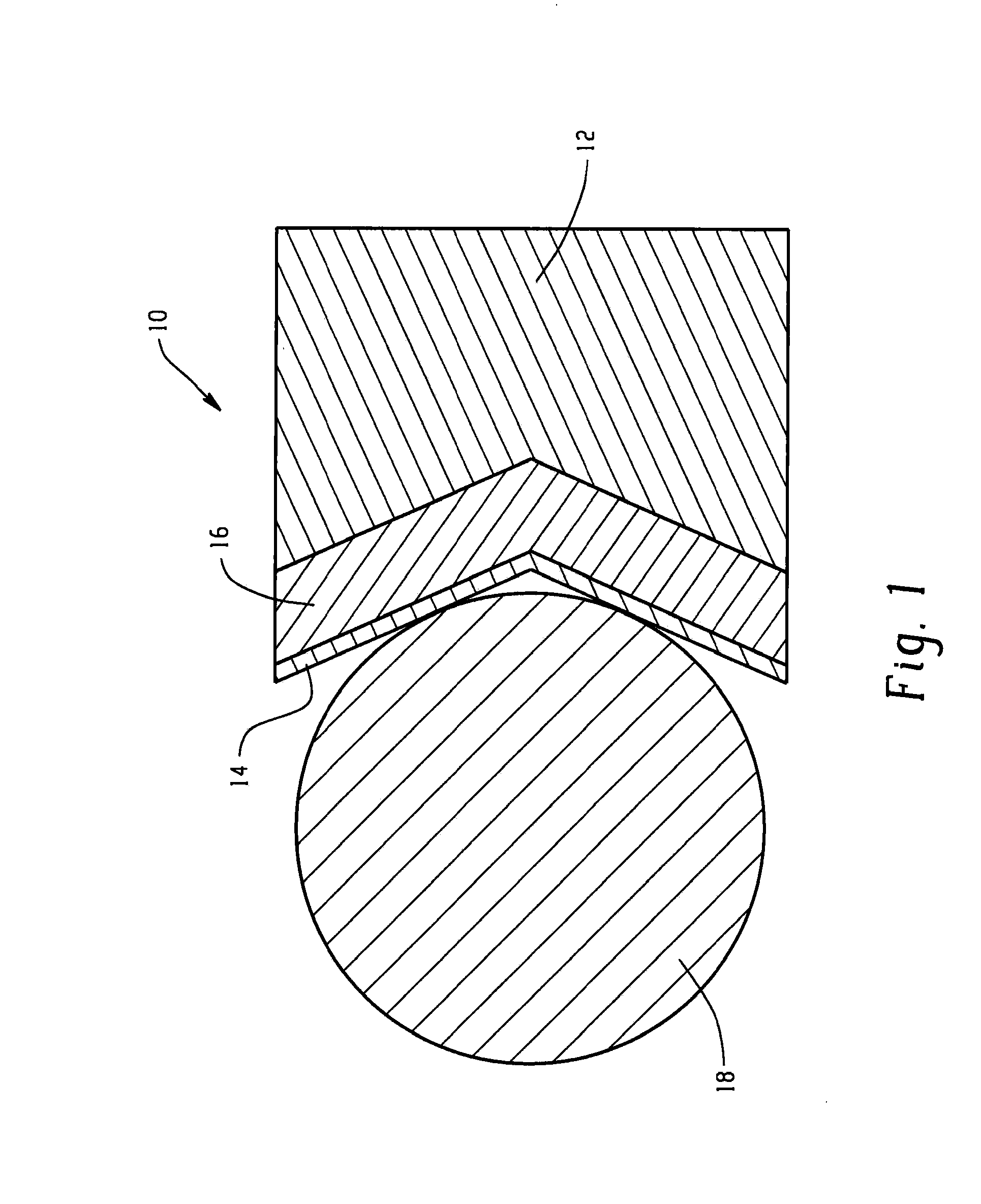
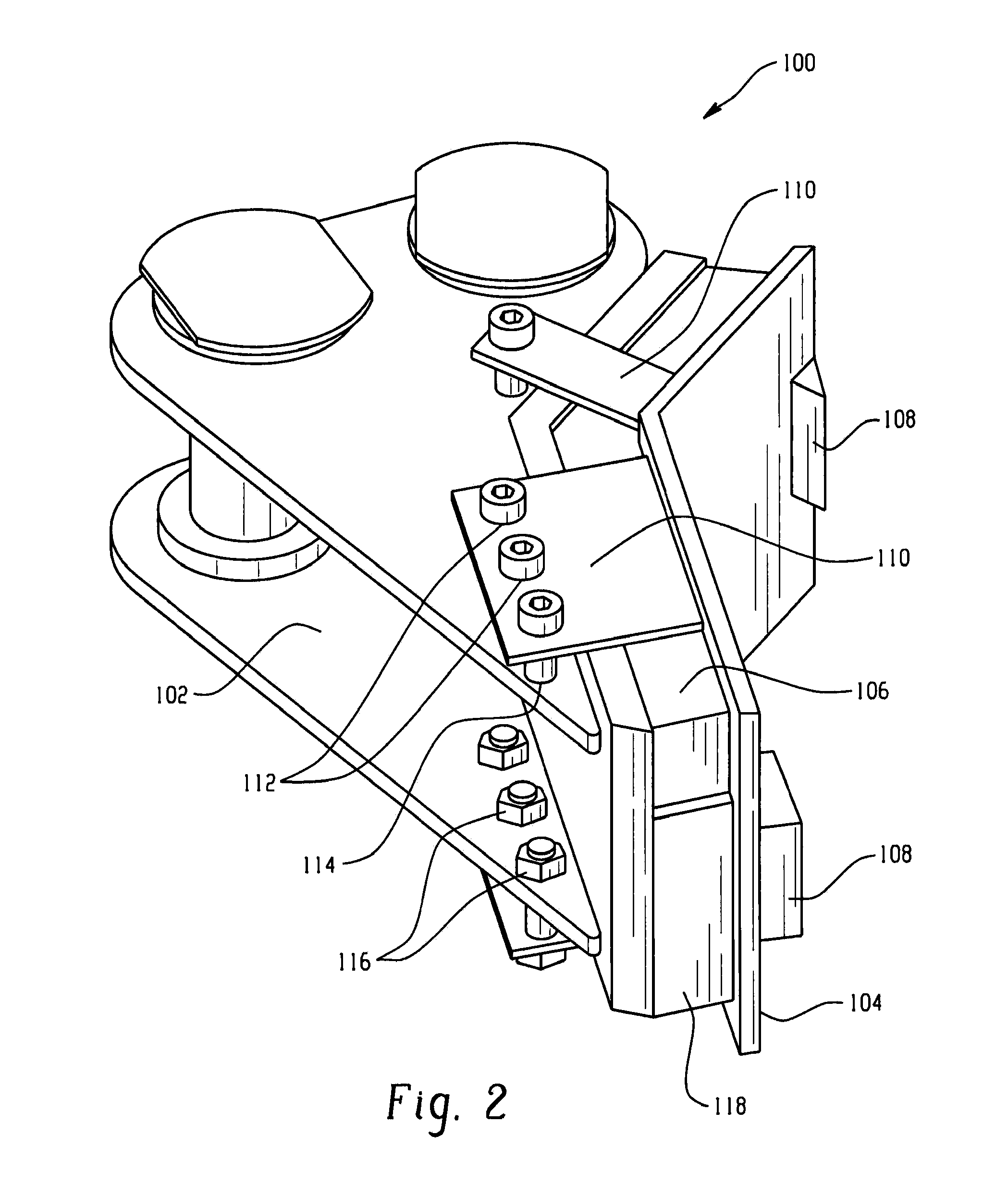
[0025]A gripper assembly in accordance with the present invention was used to transfer a cylindrically shaped metal part, which had been heated to 1800° F. in a furnace, to a work station. The gripper assembly included a contact plate having a thermal conductivity of 26 Btu per hour degree Fahrenheit foot (Btu / hr° F. ft). The contact plate had a thickness of 0.25 inches and a surface area of 45 square inches. The main body of the gripper assembly also had a thermal conductivity of 26 Btu / hr° F. ft, with a thickness of 2 inches and a surface area of 45 square inches. The insulating plate was sandwiched between the contact plate and the main body and had a thickness of 1 inch and the same 45 square inch surface area. The insulating plate had a thermal conductivity of 0.22 Btu / hr° F. ft.

example 2

[0029]The gripper assembly as described in Example 1 above was used to transfer a metal part from a furnace to a work station. The metal part had an initial temperature leaving the furnace of 1575° F. The transfer took about 16 seconds. A thermal imaging camera was used to document the temperature profile of the metal part after transfer from the furnace to the work station. The thermal image showed the upper end of the metal part's surface temperature to be about 1470° F. after transfer by the insulated gripper assembly to the work station. The temperature of the part is substantially uniform, with only four small circles of reduced temperature. Those circles correspond to the contact points of the contact plate with the metal part and represent the minor heat transfer to the contact plate.


PUM

PropertyMeasurementUnit
Fractionaaaaaaaaaa
Thicknessaaaaaaaaaa
Thicknessaaaaaaaaaa

Abstract

A gripper assembly for a forging manipulator includes a main body configured to be in operative communication with the manipulator; a contact plate attached to the main body and configured to be in physical communication with a heated metal part; and an insulating plate disposed between the main body and the contact plate, wherein the insulating plate is configured to substantially prevent heat transfer from the heated metal part to the main body.

Description

BACKGROUND[0001]The present disclosure generally relates to a gripper assembly for a manipulator and methods for using the gripper assembly. More particularly, the present disclosure relates to an insulated gripper assembly of a manipulator for manipulating metal ingots during forging.[0002]In metal forging processes, a mechanical hand, also known as a manipulator, has to pick up a rough or part-finished component and transfer it to a downstream work station. The metal parts begin as metal ingots that are heated in furnaces to temperatures over 1500 degrees Fahrenheit (F). As such, manipulators must be used to then transfer the metal ingots (also known as mults or blockers) to downstream work stations in the process, such as the forging dies, cooling stations, and the like.[0003]Such manipulators are known in forging processes and generally include, in their broadest form, a mechanical arm having at least two cooperating jaws or clamping devices positioned at one end thereof. These ...

Claims


Application Information

Patent Timeline
IPC IPC(8): B21J13/10B65G47/90
CPCB21K27/04B25J19/0075B25J15/0042B21J13/10
Inventor HEBERT, DAVIDFOLEY, II, MATTHEW LOUISMEYERS, CHRISPHAM, DIANE
Owner FIRTH RIXSON
Learn More