Placement aware clock gate cloning and fanout optimization

a clock gate and fanout optimization technology, applied in the field of clock circuits, can solve the problems of reducing the active power of the circuit, degrading the clock tree synthesis quality in clock wire length, insertion delay and clock tree divergence, etc., and achieves better clock tree synthesis quality results and better placement quality of clock gates.

Active Publication Date: 2013-07-04
TEXAS INSTR INC
View PDF2 Cites 7 Cited by
  • Summary
  • Abstract
  • Description
  • Claims
  • Application Information

AI Technical Summary

Benefits of technology

The new way of modifying designs helps improve how clock signals are placed and makes it easier for engineers to create high-quality timing diagrams.

Problems solved by technology

The technical problem addressed in this patent is reducing the power consumption of integrated circuits designed with clock signals. In traditional designs, there were often too many clock gates which negatively affected the performance of the circuit. However, through a conversion process called clock gating, the inventor found that disabling certain parts of the circuit based on their activity level reduced power consumption without affecting overall functionality or speed.

Method used


Image

  • Placement aware clock gate cloning and fanout optimization
  • Placement aware clock gate cloning and fanout optimization
  • Placement aware clock gate cloning and fanout optimization

Examples


Embodiment Construction

[0016]Shutting off the clock to a register or a bank of registers when not in a change state is a common but effective practice to reduce dynamic power in an integrated circuit. There are a lot of design considerations during implementation of the clock gates. These are a few critical aspects to be considered in the clock gating strategy:[0017]1. Dynamic power and leakage power tradeoff;[0018]2. Tradeoff between dynamic power savings and setup timing closure to the enable pins; and[0019]3. Effect of clock gating on the clock tree divergence.

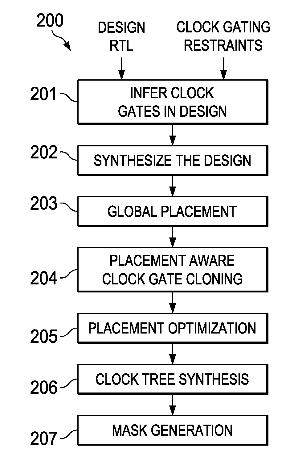
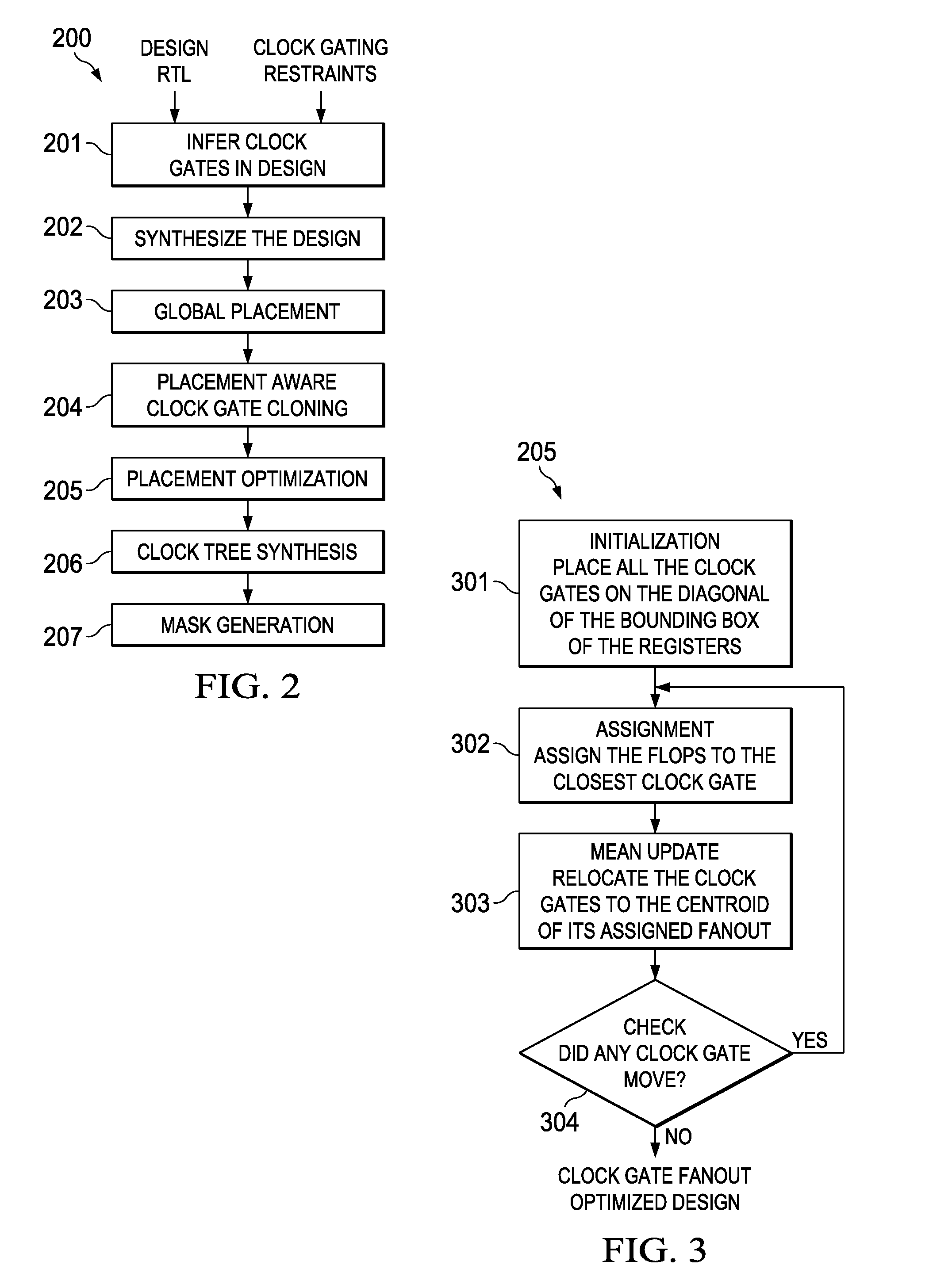
[0020]Each of these considerations impacts the quality of the clock tree of the integrated circuit in terms of insertion delay, area and divergence. This invention is a physical placement aware technique for modification of an integrated circuit design to clone / redistribute clock fanout among equivalent clock gates. This patent application describes the commonly used methods clock gate physical design with their clock tree synthesis concerns. Thi...


PUM


Abstract

Gating clocks has been a widely adopted technique for reducing dynamic power. The clock gating strategy employed has a huge bearing on the clock tree synthesis quality along with the impact to leakage and dynamic power. This invention is a technique for clock gate optimization to aid the clock tree synthesis. The technique enables cloning and redistribution of the fanout among the existing equivalent clock gates. The technique is placement aware and hence reduces overall clock wire length and area. The technique involves employing the k-means clustering algorithm to geographically partition the design's registers. This invention improves the clock tree synthesis quality on a complex design.

Description


Claims


Application Information

Patent Timeline
Owner TEXAS INSTR INC
Why Eureka
Try Eureka