
Numerical control method and numerical control device of machine tool

Active Publication Date: 2013-07-04
MAKINO MILLING MASCH CO LTD
View PDF5 Cites 16 Cited by
  • Summary
  • Abstract
  • Description
  • Claims
  • Application Information

AI Technical Summary

Benefits of technology

The invention is about a way to control the movement of a feed axis in a machine tool. By breaking down the range of movement into different regions and using different control parameters for each region, the invention can absorb any differences in the rigidity or friction of the machine parts caused by the position of the feed axis. This results in a higher level of precision and stability in the machining process, regardless of the position of the feed axis. The control parameters are determined in advance, making it easier to set the machine for stable control.

Problems solved by technology

For example, when using two perpendicularly intersecting linear feed mechanisms to make a workpiece or tool move in an arc, this phenomenon of delay generally causes the unpreferable position error called “stick motion”.

Method used


Image

  • Numerical control method and numerical control device of machine tool
  • Numerical control method and numerical control device of machine tool
  • Numerical control method and numerical control device of machine tool

Examples


Embodiment Construction

[0026]Below, referring to the attached drawings, embodiments of the present invention will be explained. In the following figures, similar members will be assigned similar reference notations. To facilitate understanding, these figures are suitably changed in scale.

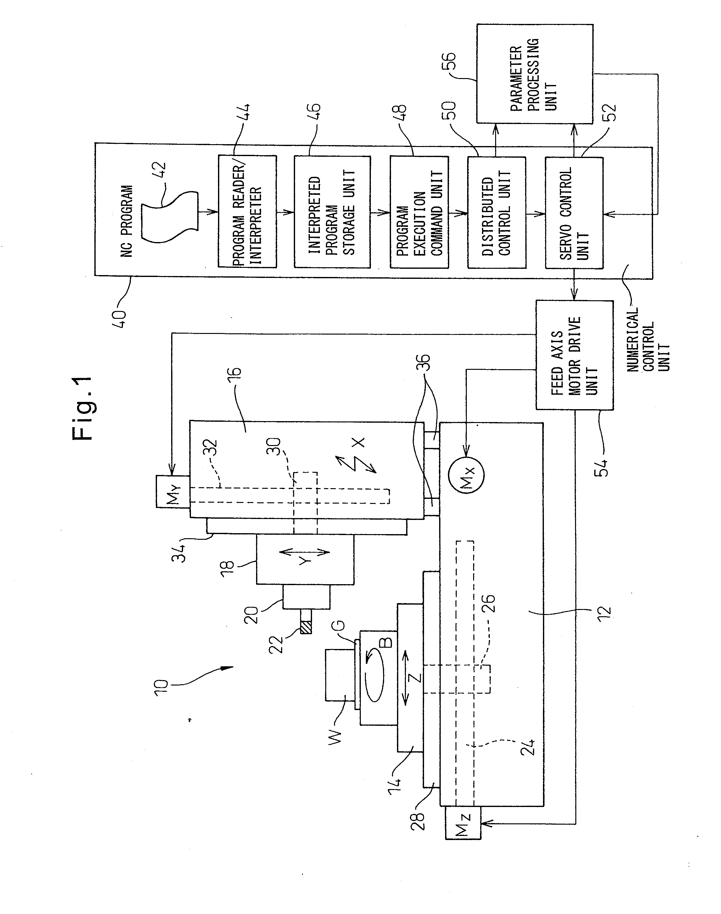
[0027]FIG. 1 is a schematic view of a numerical control machine tool 10 according to one aspect of the present invention. In FIG. 1, the numerical control machine tool 10 is a so-called horizontal machining center which is provided with a bed 12 which is placed on the floor of a factory etc. On the top surface of the bed 12, Z-axis guide rails 28 are laid in a horizontal Z-axis direction (left-right direction in FIG. 1). At the Z-axis guide rails 28, a table 14 for fastening a workpiece W through a workpiece jig G is slidably attached. FIG. 1 shows an example of fastening an NC rotary table able to rotate in a B-axis direction on the table 14 and placing a workpiece W on top of that, but a workpiece W may be directly plac...


PUM


Abstract

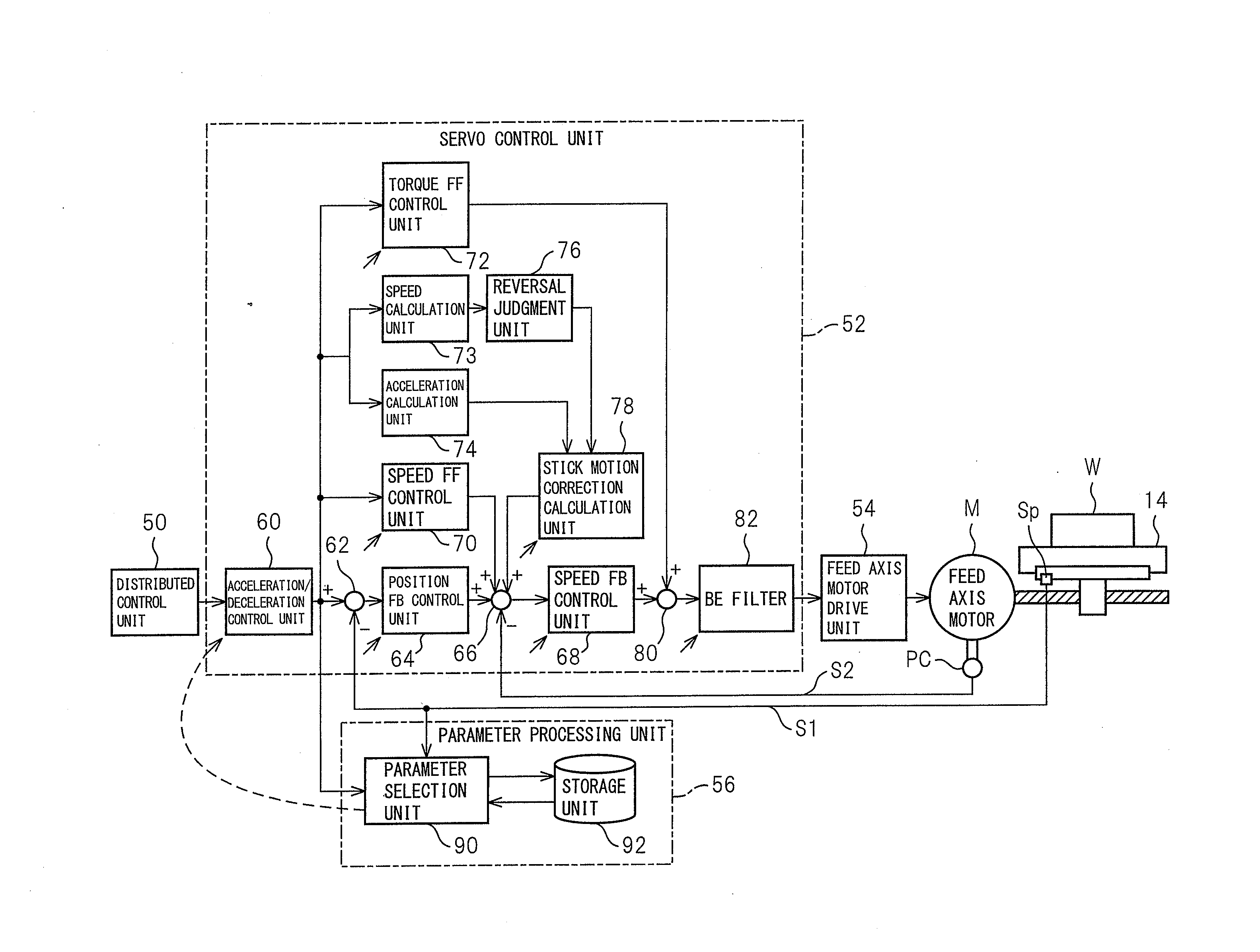
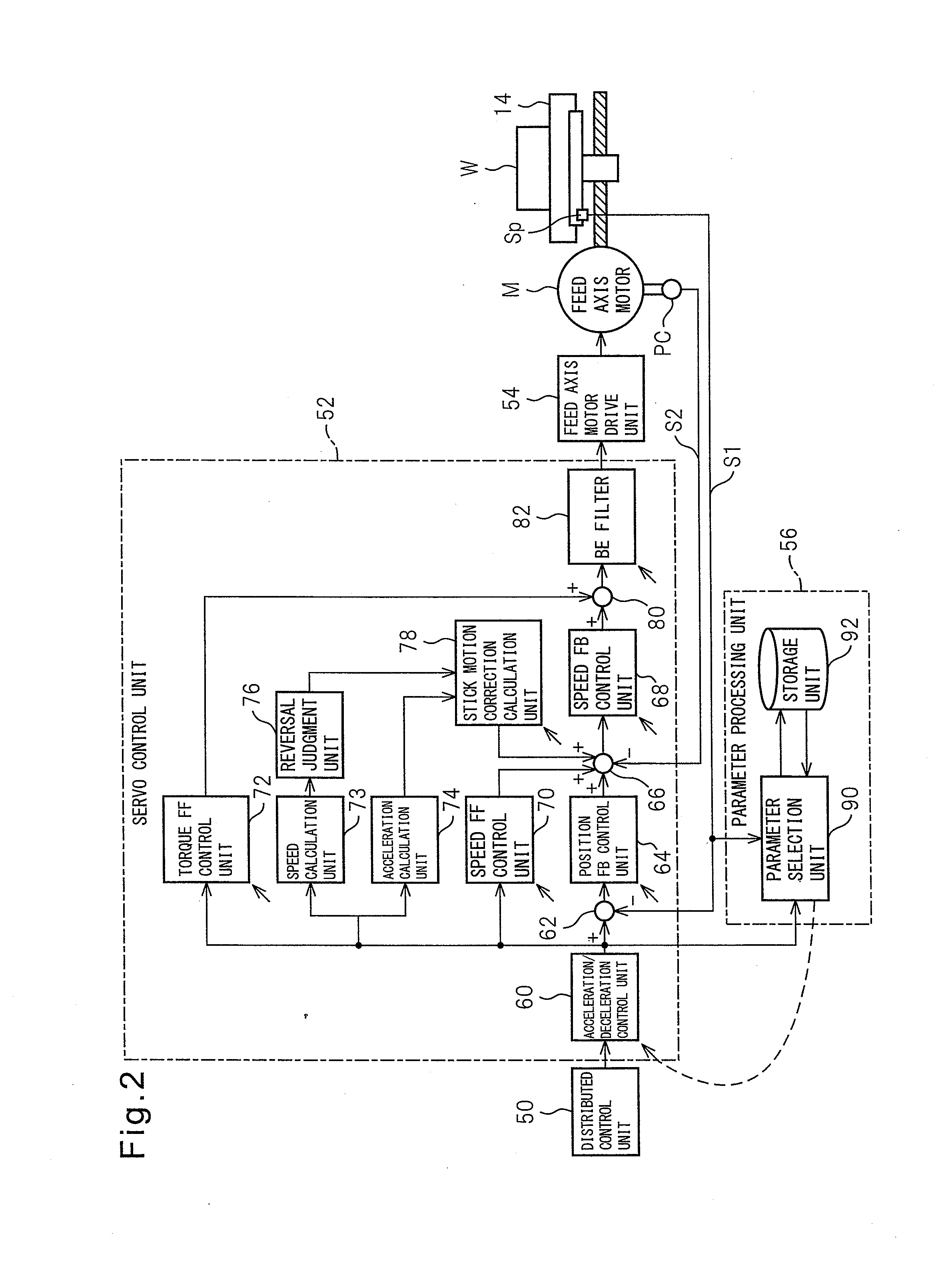
A numerical control device which controls a feed axis of a machine tool (10) has a storage unit (92) which divides a range of movement of the feed axis into a plurality of regions and stores a plurality of control parameters corresponding to said divided plurality of regions in advance, a position detection unit which detects a position of a feed axis at the time of machining a workpiece, a parameter selection unit (90) which reads out control parameters corresponding to a divided region to which the detected feed axis position at the time of machining a workpiece belongs, and a servo control unit (52) which controls the feed axis using said read control parameters. Due to this, it is possible to provide a numerical control method of a machine tool which realizes stable machining precision without regard as to the feed axis position and a numerical control device which conducts that method.

Description

REFERENCE TO RELATED APPLICATIONS[0001]This application is the national stage application under 35 USC 371 of International Application No. PCT / JP2011 / 074698, filed Oct. 26, 2011, which claims priority from Japanese Patent Application No. 2010-241388, filed Oct. 27, 2010, the entire contents of which are incorporated herein by reference.TECHNICAL FIELD OF THE INVENTION[0002]The present invention relates to a numerical control method which controls a feed axis of a machine tool and a numerical control device which conducts that method.BACKGROUND OF THE INVENTION[0003]A machine tool includes at least one feed mechanism for making a workpiece and a tool move relative to each other. The motor for driving the feed mechanism is controlled by a numerical control device. When a feed direction of the workpiece or tool is reversed by the feed mechanism, the direction of action of frictional force between the relatively moving parts included in the feed mechanism (for example, the feed screw a...

Claims


Application Information

Patent Timeline
IPC IPC(8): G05B19/18
CPCG05B19/404G05B19/182G05B2219/41078G05B2219/49182G05B2219/41155G05B2219/42039G05B2219/41083G05B2219/41206
Inventor KAWANA, AKIRAMORI, NORIOODA, MITSUNARI
Owner MAKINO MILLING MASCH CO LTD
Learn More