
Medical robotic system and control method thereof

a robotic system and medical technology, applied in the field of medical robot systems, can solve the problems of inability to guarantee the safety of the incision region of the patient may be injured during surgery, and the medical robot system does not provide the location of the surgical instrument in the incision region, so as to improve the safety of robotic surgery

Active Publication Date: 2013-07-04
SAMSUNG ELECTRONICS CO LTD
View PDF24 Cites 27 Cited by
  • Summary
  • Abstract
  • Description
  • Claims
  • Application Information

AI Technical Summary

Benefits of technology

The present invention provides a medical robot system that can detect the position of a surgical instrument in an incised region to improve the safety of robotic surgery. The robot control mode can be selected from stopping motion, moving by a distance less than a commanded distance, or reducing the speed of motion. The control system can generate a control signal based on the input command while keeping the position of the instrument within a predetermined reference range or adjusting it on a boundary or outside of the range. These features enhance the accuracy and precision of the robot system during surgery procedures.

Problems solved by technology

However, such a conventional medical robot system does not guarantee the safety of an incised region of the patient.
Specifically, when the operator inserts the surgical instrument into the incised region of the patient and incises or stitches a region for surgery, the conventional medical robot system does not provide a location of the surgical instrument in the incised region.
For this reason, the operator does not know the location of the surgical instrument in the incised region while controlling a motion of the robot arm, and therefore, the incised region of the patient may be injured during surgery.
Also, the doctor may have difficulty controlling motion of the robot or the robot arm so as not to injure the incised region of the patient, and therefore, fatigue due to the use of the surgical robot may increase, which may result in an operator error during performance of the surgery.

Method used


Image

  • Medical robotic system and control method thereof
  • Medical robotic system and control method thereof
  • Medical robotic system and control method thereof

Examples


Embodiment Construction

[0038]Advantages and features of the present invention and a method of achieving the advantages and the features will be apparent by referring to embodiments described below in detail in connection with the accompanying drawings. However, the present invention is not limited to the embodiments disclosed below, but may be implemented in various forms. The embodiments disclosed here complete the disclosure of the present invention, and is provided to clearly inform those skilled in the art of the scope of the invention. The present invention is defined by the scope of the claims.

[0039]Reference will now be made in detail to the embodiments of the present invention, examples of which are illustrated in the accompanying drawings, wherein like reference numerals refer to like elements throughout.

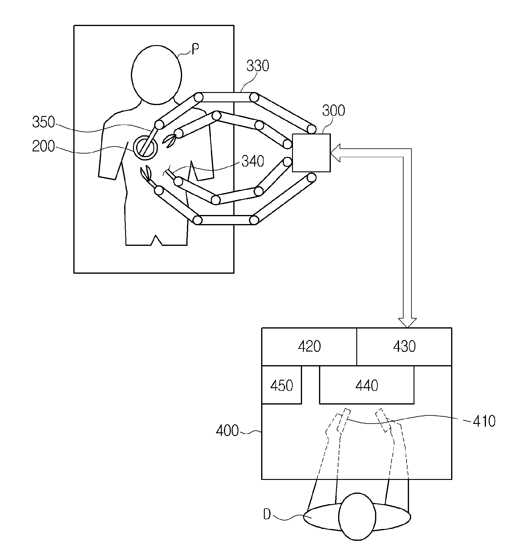
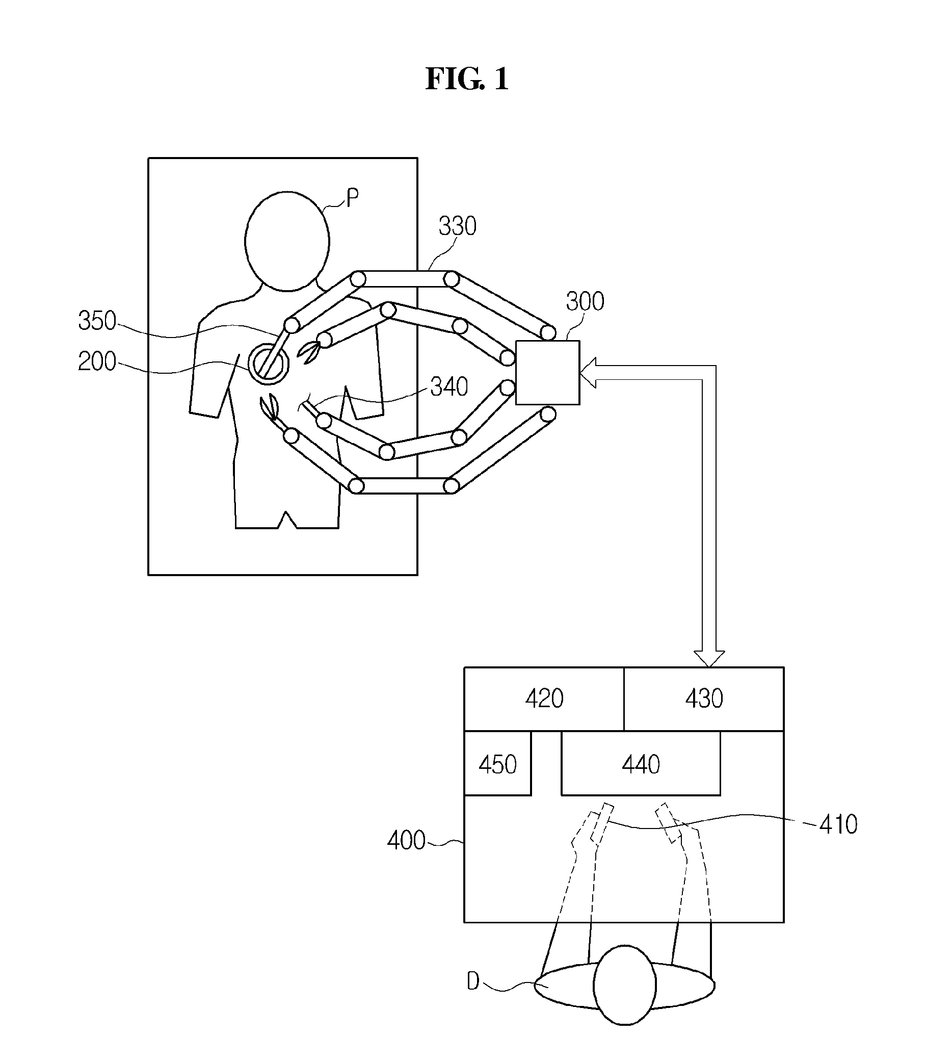
[0040]FIG. 1 is a view showing the construction of a medical robot system according to an embodiment of the present invention.

[0041]As shown in FIG. 1, the medical robot system may include a cons...


PUM


Abstract

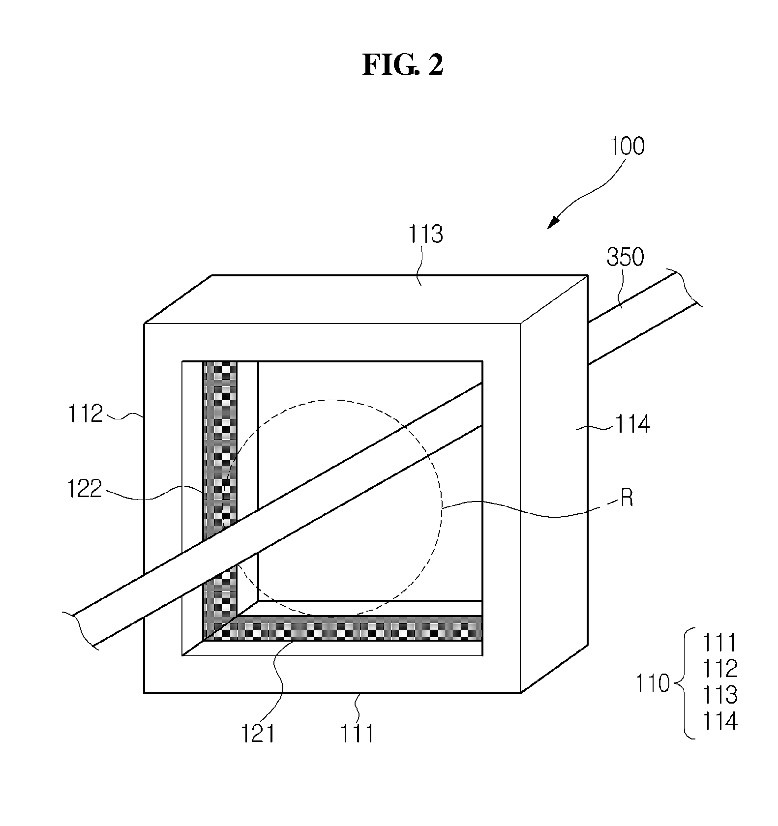
A medical robot system and a method to control the medical robot system are used to detect position information of a surgical instrument in an incised region, thereby improving the safety of robotic surgery. A surgical instrument may be inserted in a through-hole of a trocar inserted into an incised region of a patient. The medical robotic system includes a surgical instrument position detection apparatus to detect position information of the surgical instrument in the through-hole of the trocar, when the surgical instrument is inserted into the through-hole. The medical robotic system further includes a console to control an operation of a surgical robot having the surgical instrument, based on the detected position information of the surgical instrument.

Description

CROSS-REFERENCE TO RELATED APPLICATIONS[0001]This application claims the priority benefit of Korean Patent Application No. 10-2011-0145455, filed on Dec. 29, 2011, in the Korean Intellectual Property Office, the disclosure of which is incorporated herein by reference.BACKGROUND[0002]1. Field[0003]Embodiments disclosed herein relate to a medical robot system that improves safety of robotic surgery and a control method thereof.[0004]2. Description of the Related Art[0005]Robotic surgery is a type of surgery that a medical professional (e.g., a surgeon or doctor) performs while controlling a robot to move a surgical instrument and is applied to various medical fields including surgery.[0006]Generally, a medical robot system includes a robot including a robot arm and a console for an operator (e.g., a medical professional) to control the motion of the robot. An operator may directly move the robot arm having a surgical instrument or remotely control a motion of the robot arm through man...

Claims


Application Information

Patent Timeline
Patent Type & Authority Applications(United States)
IPC IPC(8): G01B11/14A61B19/00
CPCA61B17/3403A61B19/30A61B2019/202A61B2019/2296A61B2019/5231A61B2019/5272A61B2019/5255A61B19/2203A61B2017/3445A61B2019/4857A61B19/5244A61B2019/5257G01B11/14A61B90/13A61B2090/373A61B2034/2055A61B2034/2057A61B2034/2072A61B34/20A61B2034/301A61B34/30A61B34/77A61B90/03A61B2090/0811B25J13/06B25J13/08B25J9/02A61B2017/348A61B17/3494
Inventor SANG, TAE JUNLEE, KWANG KYUKWON, WOONGROH, KYUNG SHIK
Owner SAMSUNG ELECTRONICS CO LTD
Learn More