
Hybrid passive optical network system

a passive optical network and hybrid technology, applied in the field of hybrid wavelength division multiplexing (w), can solve the problems of high capital expenditure, wdm-pon technology, and the change of optical transmitter and optical receiver hardwar

Inactive Publication Date: 2013-07-04
ELECTRONICS & TELECOMM RES INST
View PDF6 Cites 101 Cited by
  • Summary
  • Abstract
  • Description
  • Claims
  • Application Information

AI Technical Summary

Benefits of technology

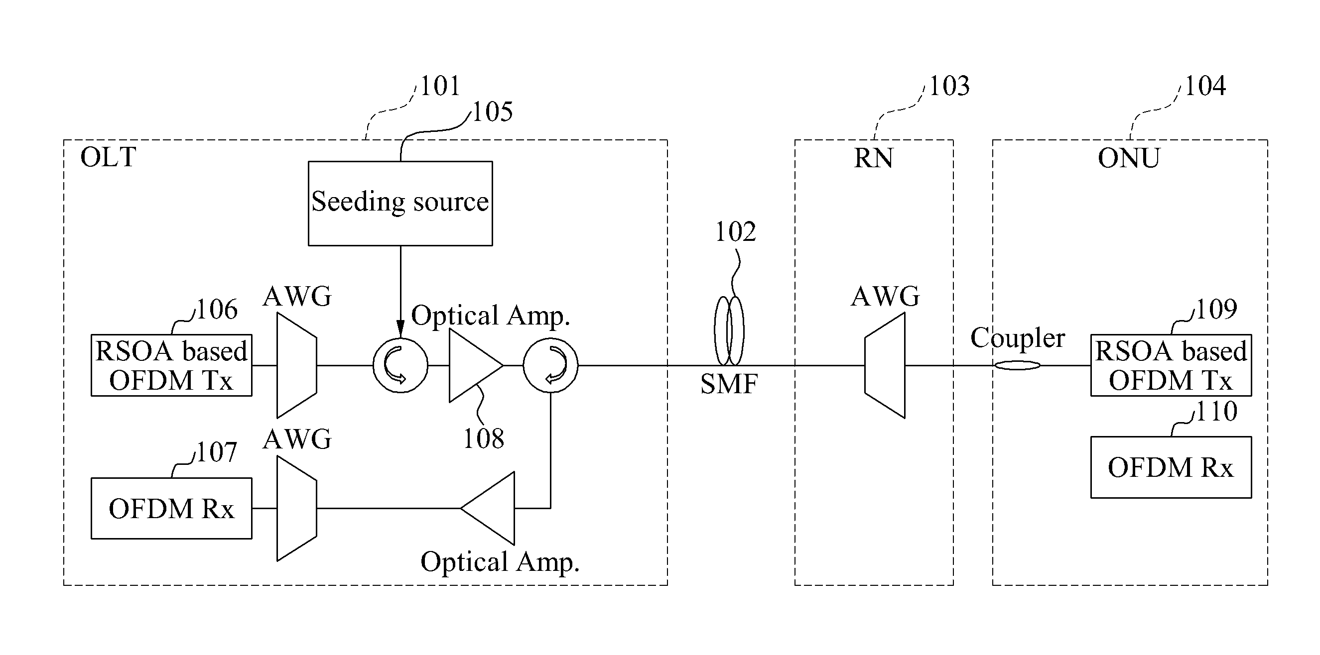
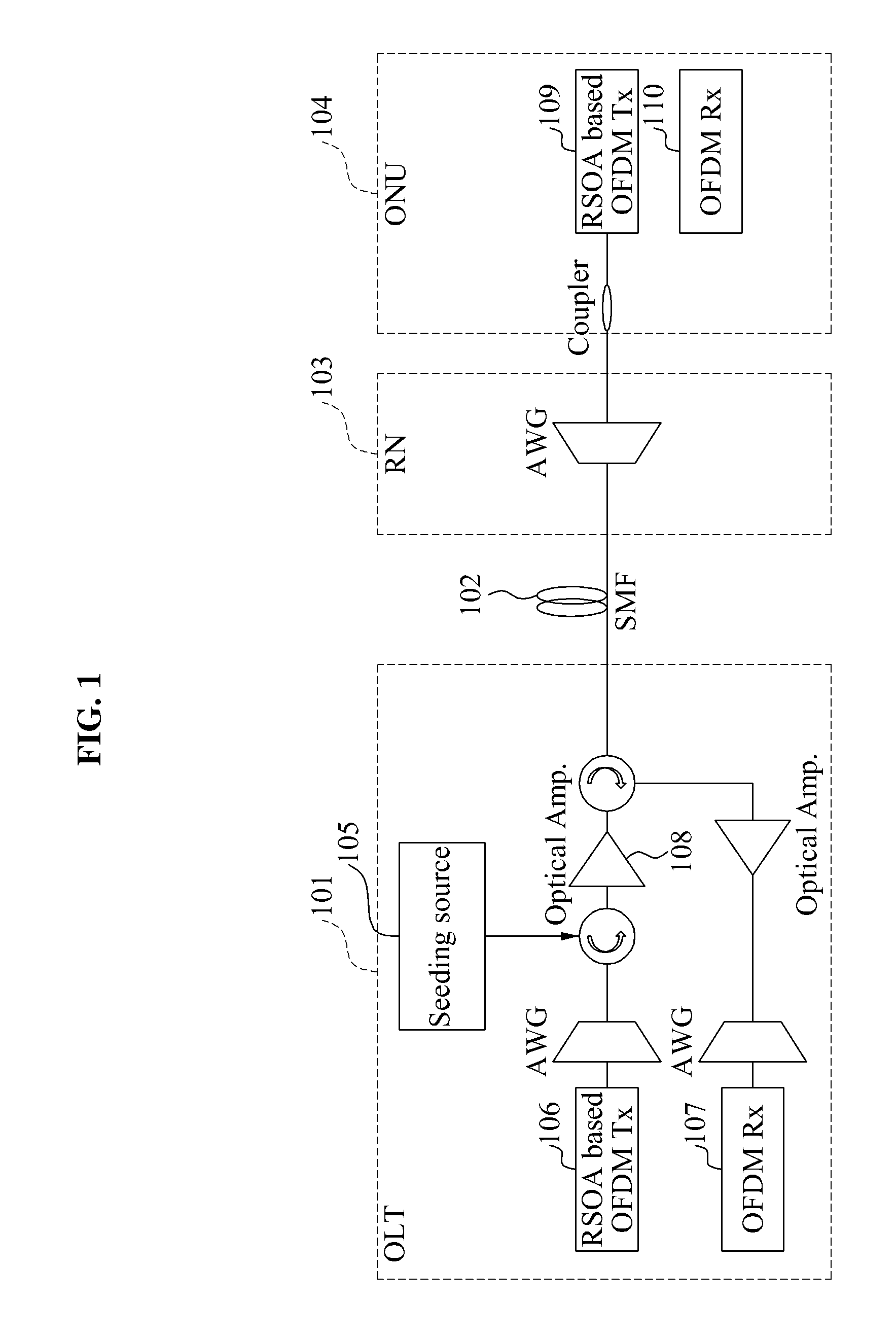
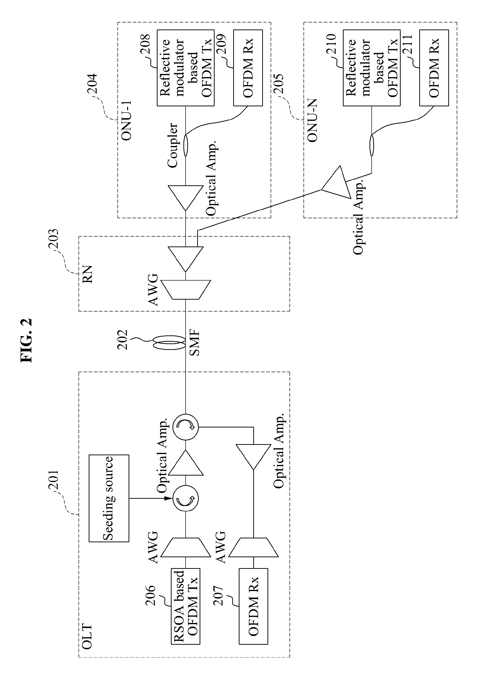
The present invention provides a hybrid PON system using a combination of wavelength division multiplexing (WDM) and time division multiplexing (TDM) optical modes. The system includes an optical line terminal (OLT) and multiple optical network units (ONUs). The OLT transmits a continuous wavelength (CW) light to the ONUs using a reflective modulator, and the ONUs modulate the CW light using a reflective modulator and transmit an OFDM downstream signal to the OLT. The OLT also receives an OFDM upstream signal from each ONU and reuses a portion of the downstream signal as an upstream signal. The system can provide efficient use of network resources and improved transmission quality.

Problems solved by technology

For these reasons, upgrading of a system to meet additional bandwidth requirements is usually achieved in an aspect of hardware, which may impose an economical burden on a subscriber and may be an obstruction to system expansion and network re-construction and dynamic resource allocation for traffic control for efficient use of transmission resources.
These additional technologies may result in a high capital expenditure.
The TDM-PON technology has an advantage of adaptively responding to a change in bandwidth required per subscriber since the TDM-PON technology provides a dynamic bandwidth allocation function, but has a disadvantage of having to change optical transmitter and optical receiver hardware when a maximum convergence bandwidth is increased.
However, a WDM-PON technology has disadvantages of lower network flexibility and a higher average installation cost per subscriber than a TDM-PON technology in that a bandwidth provided to each subscriber is determined based on a wavelength and a physical bandwidth limit of a light source allowing fast modulation.
Also, an issue associated with additional physical layer compensation technologies for providing a high-speed bandwidth per wavelength will be happened.

Method used


Image

  • Hybrid passive optical network system
  • Hybrid passive optical network system
  • Hybrid passive optical network system

Examples


Embodiment Construction

[0032]The invention is described more fully hereinafter with reference to the accompanying drawings, in which exemplary embodiments of the invention are shown. This invention may, however, be embodied in many different forms and should not be construed as limited to the embodiments set forth herein. Rather, these exemplary embodiments are provided so that this disclosure is thorough, and will fully convey the scope of the invention to those skilled in the art. In the drawings, the size and relative sizes of layers and regions may be exaggerated for clarity. Like reference numerals in the drawings denote like elements.

[0033]It will be understood that when an element is referred to as being “connected to” another element, it can be directly connected to the other element, or intervening elements may be present.

[0034]The present invention may have the following exemplary embodiments.

[0035](1) a hybrid passive optical network (PON) system including a seed light source supporting a singl...


PUM


Abstract

Provided is a hybrid passive optical network (PON) system. The hybrid PON system of wavelength division multiplexing (WDM) / time division multiplexing (TDM) may include an optical line terminal (OLT) and an optical network unit (ONU). The OLT and the ONU may transmit a signal based on wavelength reuse using a seed light source and a reflective modulator. The light source may include a seed light source having a single wavelength, two seed light sources having different wavelength bands, and a light source having a wavelength tunable characteristic.

Description

CROSS-REFERENCE TO RELATED APPLICATION[0001]This application claims priority from and the benefit of Korean Patent Application No. 10-2011-0147648, filed on Dec. 30, 2011, which is hereby incorporated by reference for all purposes as if fully set forth herein.BACKGROUND OF THE INVENTION[0002]1. Field of the Invention[0003]Exemplary embodiments of the present invention relate to a network architecture of a high-speed optical network system, and in particular, to a hybrid wavelength division multiplexing (WDM) / time division multiplexing (TDM) passive optical network (PON) system using an orthogonal frequency division multiplexing (OFDM)-based optical modem as a main method of transfer.[0004]2. Discussion of the Background[0005]A passive optical network (PON) is mainly built from a passive device having low power consumption, and uses an optical fiber as a main transmission medium. The PON may maximize a physical transmission bandwidth, and may ensure economical maintenance and repair,...

Claims


Application Information

Patent Timeline
IPC IPC(8): H04J14/02
CPCH04J14/0278H04J14/02H04J14/0246H04J14/0247H04J2014/0253H04J14/0252H04J14/0282H04J14/0298H04J14/025H04B10/25H04L27/26
Inventor CHO, SEUNG-HYUNLEE, JIE HYUNMYONG, SEUNG ILLEE, SANG SOOLEE, JONG HYUNJUNG, EUI SUKKIM, KWANG OK
Owner ELECTRONICS & TELECOMM RES INST
Learn More