
Temporary toilet

Inactive Publication Date: 2013-07-04
NAKAYA MASAYUKI
View PDF17 Cites 23 Cited by
  • Summary
  • Abstract
  • Description
  • Claims
  • Application Information

AI Technical Summary

Benefits of technology

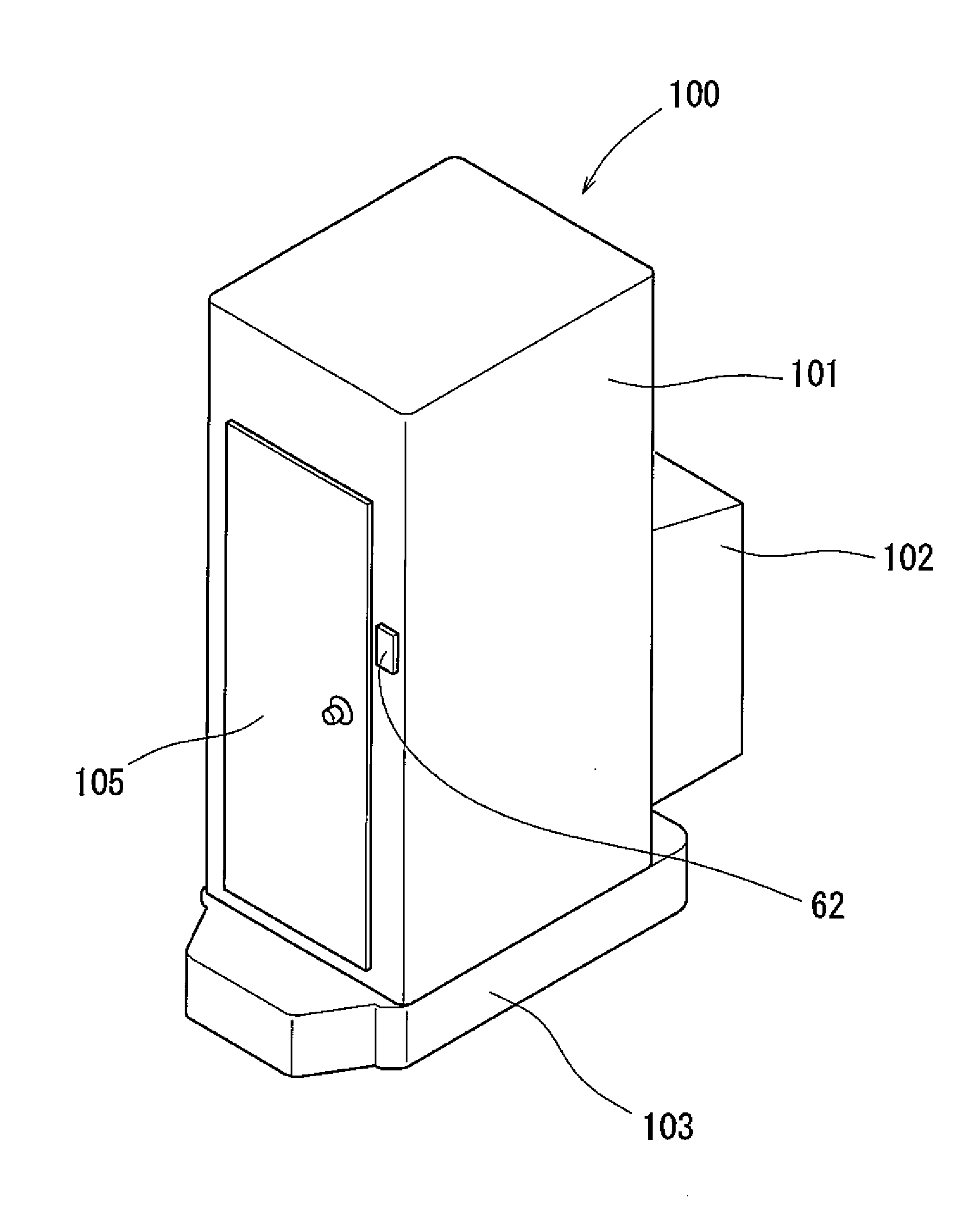
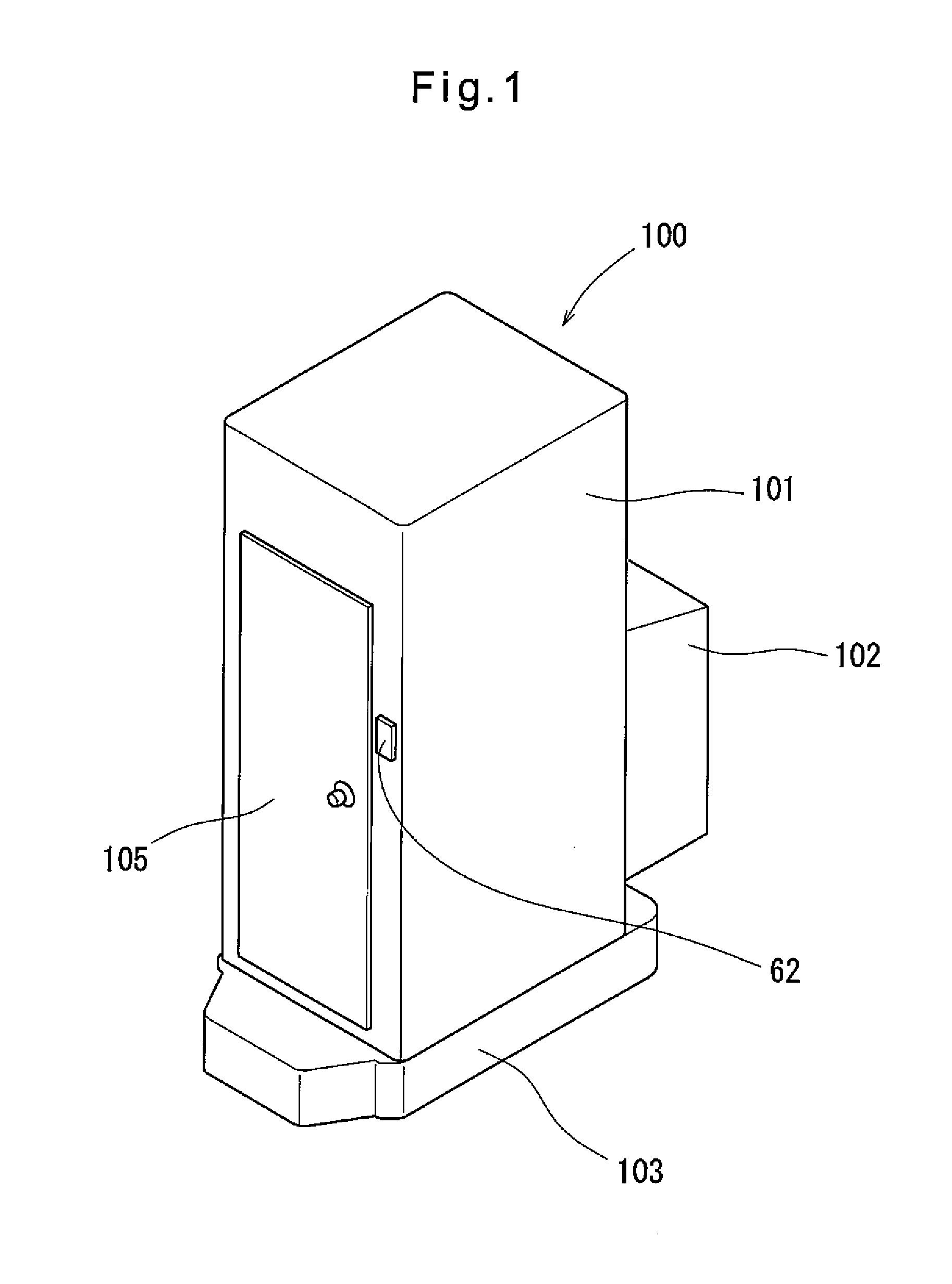
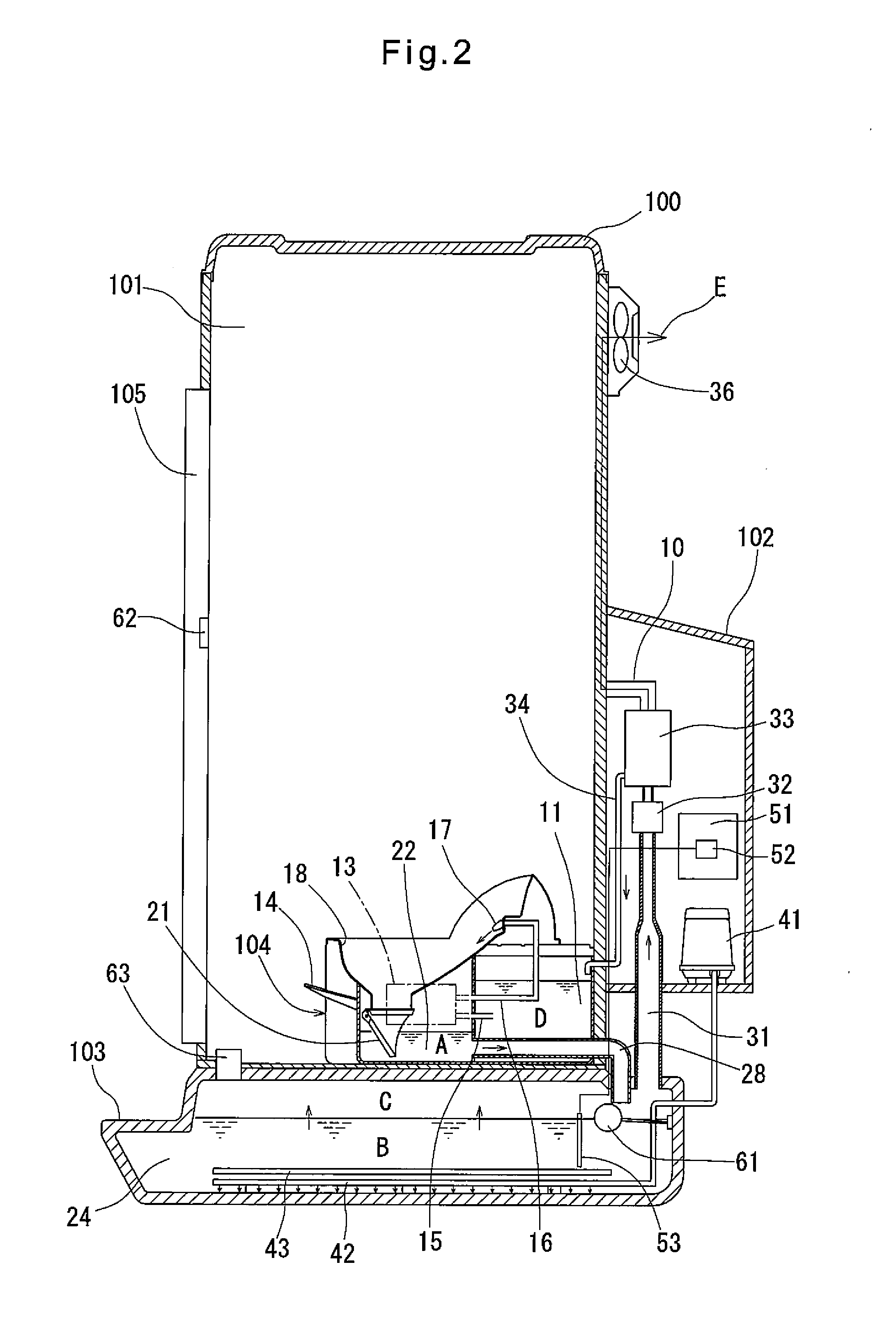
The present invention provides a temporary toilet that is compact in size, easily transportable, and can be installed in areas where there is no permanent water supply system or frequent maintenance. The toilet system includes a toilet bowl, flush water tank, sewage tank, water vapor separator, exhaust pipe, and water supply pipe. The toilet system also uses microorganisms to biologically decompose the sewage and produce heat, which can be used to evaporate the flush water and maintain the water level in the system. The toilet system produces far less odor than other temporary toilets and can be installed in places where humans do not live on a permanent basis. The toilet system may also include solar cells and battery for storing electricity.

Problems solved by technology

While the toilet system disclosed in either of Patent documents 1 and 2 can sufficiently deodorize and decolor waste produced, it is large in size.
Thus, the treatment mechanism of this toilet system, including treatment tanks, is inevitably larger in size than the toilet body itself.
There are a large number of component parts that need periodical maintenance.
It is therefore troublesome and time-consuming both to install this toilet system and to maintain it.
For these reasons, neither of these toilet systems can be installed in areas where once the toilet system is installed, it has to be left unattended for a long period time, such as on riverbeds, campsites, mountain trails, etc.
These toilet systems are therefore cannot be practically used as temporary toilets in view of the difficulty in storage, transportation and operation.
But even in such places, because the above toilet systems are heavy and large in size, locations where they can be installed are limited.
If a large number of women use this toilet, the waste from the toilet bowl dramatically increases, thus shortening the intervals between maintenances.
Thus, this toilet cannot be installed where it cannot be connected to a water supply system.

Method used


Image

  • Temporary toilet
  • Temporary toilet
  • Temporary toilet

Examples


examples

[0064]Description is made of the specific amounts of water used in the various locations of each of the first and second embodiments. First regarding the first embodiment, 500 cc of water was flushed per use. The water content in the sewage tank 24 was 400 liters. The toilet was used about 60 times over a period of one week. 40 liters of waste was introduced into the sewage tank 24 per day on the average, and 30 liters of water was returned to the flush water tank 11 as flush water, whose capacity was 40 liters, per day on the average. 75% of the sewage introduced into the sewage tank 24 was recovered as flush water. During the one-week period, the total amount of water stored in various locations of the entire toilet unit 100 changed little.

[0065]Now regarding the second embodiment, 500 cc of water was flushed per use as in the first embodiment. The water content in the sewage tank 24 was 600 liters. The sewage tank 24 was used for two of the toilet booths 101 over a period of one ...


PUM

PropertyMeasurementUnit
Temperatureaaaaaaaaaa
Angleaaaaaaaaaa
Levelaaaaaaaaaa

Abstract

A compact and easily transportable temporary flush toilet can be installed where the toilet cannot be connected to a water supply system and no frequent maintenance is possible. The temporary toilet includes a toilet bowl, a flush water tank for storing flush water used to flush the toilet bowl, a sewage tank for storing sewage from the toilet bowl, a water vapor separator for separating water from gas containing water vapor vaporized from sewage in the sewage tank, an exhaust pipe through which gas is guided from the top of the sewage tank to the water vapor separator, and a distilled water pipe through which water separated from the gas in the water vapor separator is supplied to the flush water tank. Thus, storage of the sewage, microbial decomposition of waste, and evaporation of the sewage take place in the sewage tank alone.

Description

TECHNICAL FIELD[0001]The present invention relates to a flush toilet which can be continuously used without supplying additional water from outside.BACKGROUND ART[0002]Toilets are essential in order to maintain hygiene of an environment where humans live. In order to maintain high standards of living where the population density is high, flush toilets are indispensable, instead of toilets of the type which are eventually simply dumped into the environment. But in rural communities which are far from cities and cannot afford to construct a sewage system, toilets are often used having a sewage treatment tank in which waste is decomposed utilizing microorganisms. It is also being considered to use sewage as flush water for flush toilets so that flush toilets can be installed in areas where it is difficult to construct a water supply system.[0003]For example, Patent document 1 discloses a heating / evaporation type toilet system including a flow type waste tank in which waste from a toile...

Claims


Application Information

Patent Timeline
IPC IPC(8): E03D5/00
CPCE03D7/00C02F1/048C02F3/1242E03D5/016C02F2201/009C02F2203/008E04H1/1216E03D5/00B01D53/26B01D53/261B01D53/265B01D2253/106B01D2258/06C02F2209/42Y02W10/37Y02A20/212Y02W10/10
Inventor NAKAYA, MASAYUKI
Owner NAKAYA MASAYUKI
Learn More