Dynamic Exoskeletal Orthosis

a technology of exoskeleton and orthosis, applied in the field of dynamic exoskeleton orthosis, can solve the problems of severe limitation of the bracing options for those with pain/weakness/decreased range of motion about the ankle, and not allowing a more normal gait or higher level activities, so as to achieve greater ability to walk and run, and severe lower extremity physical impairment

Active Publication Date: 2013-06-27
USA AS REPRESENTED BY THE SEC OF THE ARMY ON BEHALF OF USAMRMC
View PDF28 Cites 9 Cited by
  • Summary
  • Abstract
  • Description
  • Claims
  • Application Information

AI Technical Summary

Benefits of technology

[0013]An advantage of the present invention is that the dynamic exoskeletal orthosis allows greater ability to walk and run despite severe lower extremity physical impairments.
[0014]Another advantage of the present invention is that the dynamic exoskeletal orthosis allows for early walking post-injury to high level activities with the same orthosis.
[0015]Yet another advantage of the present invention is that the dynamic exoskeletal orthosis may be lightweight, durable (tolerates impact of running with a ruck sack, for example, up to about 120 lbs.), and may be used in regular shoes and military boots.
[0016]As used herein “substantially”, “relatively”, “generally”, “about”, and “approximately” are relative modifiers intended to indicate permissible variation from the characteristic so modified. They are not intended to be limited to the absolute value or characteristic which it modifies but rather approaching or approximating such a physical or functional characteristic.
[0017]In this detailed description, references to “one embodiment”, “an embodiment”, or “in embodiments” mean that the feature being referred to is included in at least one embodiment of the invention. Moreover, separate references to “one embodiment”, “an embodiment”, or “embodiments” do not necessarily refer to the same embodiment; however, neither are such embodiments mutually exclusive, unless so stated, and except as will be readily apparent to those skilled in the art. Thus, the invention can include any variety of combinations and / or integrations of the embodiments described herein.

Problems solved by technology

Historically, bracing options for those with pain / weakness / decreased range of motion about the ankle have been severely limited.
The most common types of bracing either provided adequate strength compensation in the instance of an isolated peroneal neuropathy or were designed with very stiff orthotic materials that essentially immobilized the ankle and did not allow a more normal gait or higher level activities.

Method used


Image

  • Dynamic Exoskeletal Orthosis
  • Dynamic Exoskeletal Orthosis
  • Dynamic Exoskeletal Orthosis

Examples


Embodiment Construction

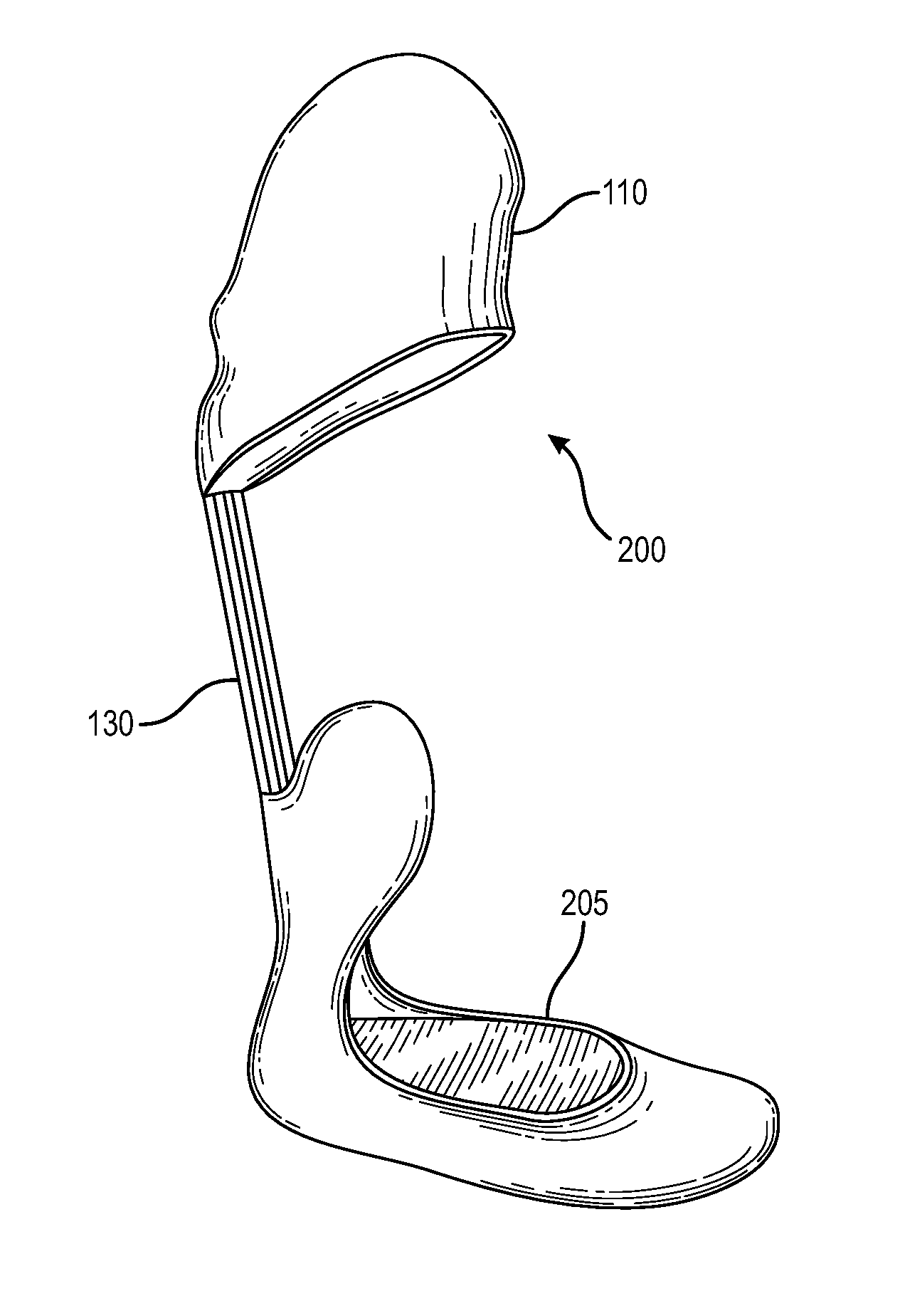
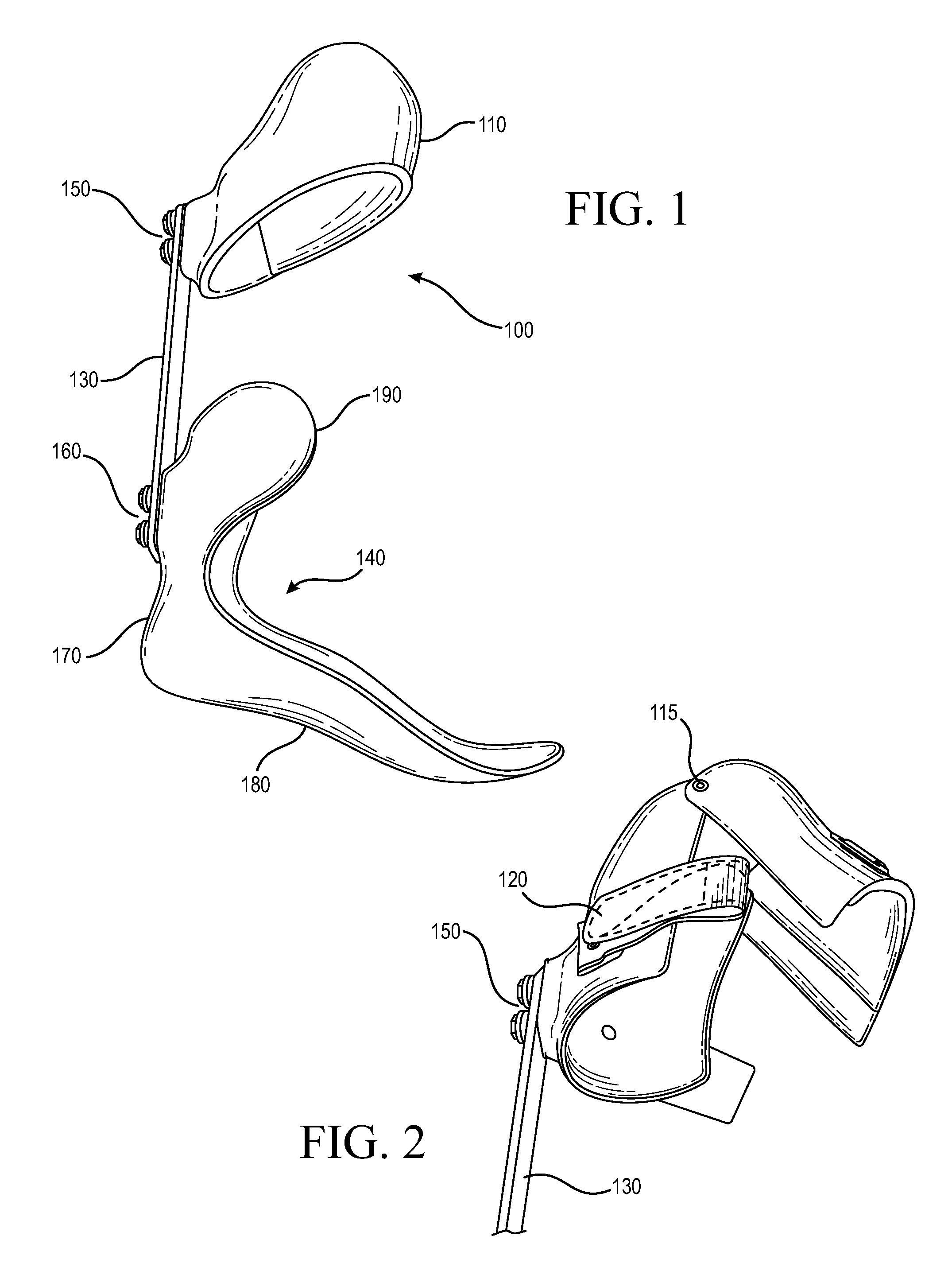
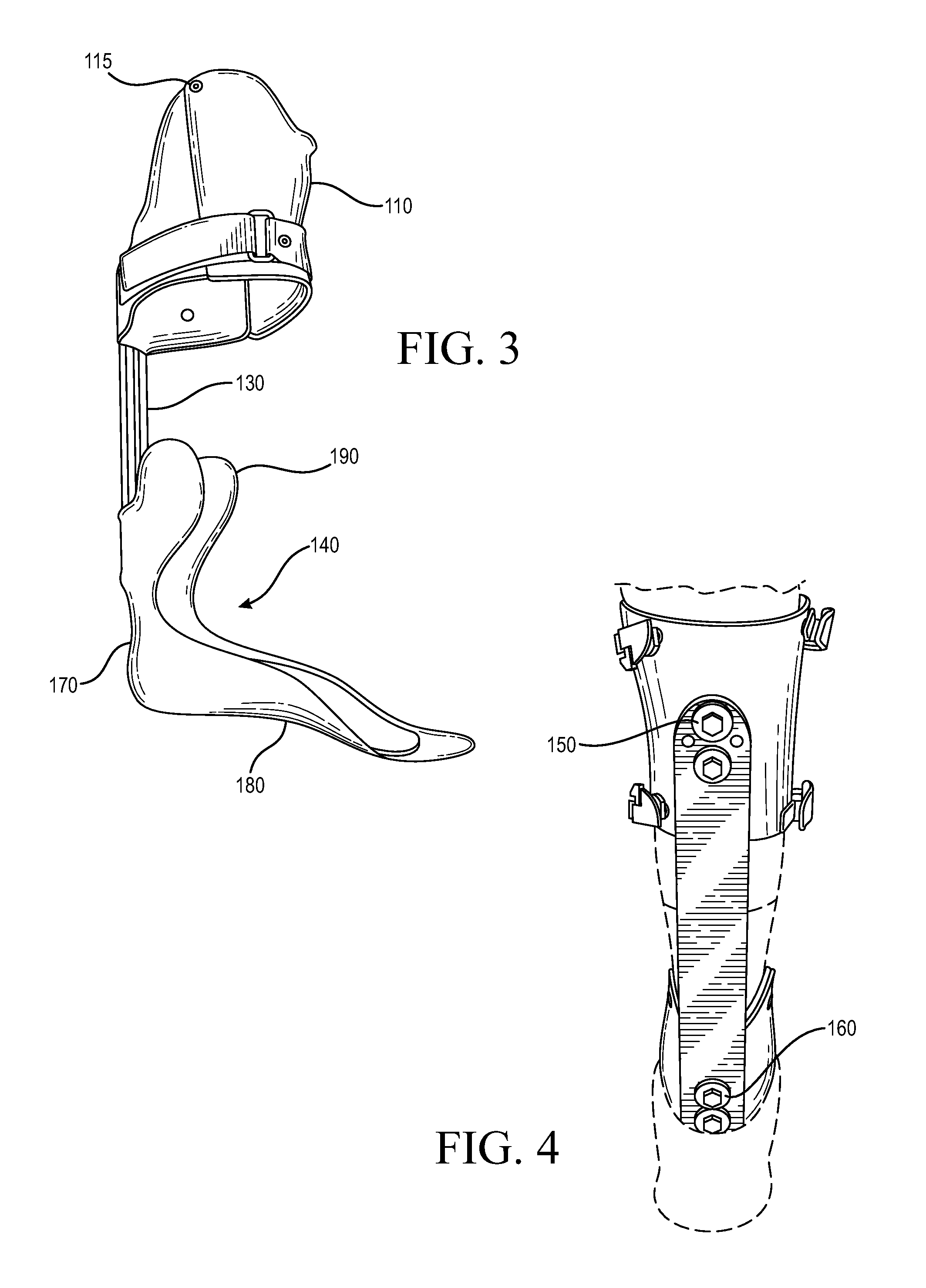
[0038]The orthosis of the present invention is designed to allow walking and running for individuals or patients with severe injury to the lower limb that causes reduced ankle range of motion, weakness, and pain. The orthosis allows for a range of activities including, but not limited to, at least one of early ambulation during an early post-injury phase, agility and impact activities, running, sprinting, or deploying with a military unit.

[0039]The orthosis of the present invention is designed to compensate for weakness, pain, and / or decreased range of motion (either alone or in combination) at the ankle that result from a variety of potential diagnoses including, but not limited to, at least one of ankle fusion, talus or calcaneus fractures, tibial nerve injuries, peroneal nerve injuries, partial foot amputation (which results in ankle plantarflexion weakness), soft tissue loss in the leg (resulting in inherent weakness), or pain in the ankle during weight bearing activities.

[0040]...


PUM


Abstract

An exoskeletal orthosis includes a proximal cuff comprising a hinge along an upper edge of the cuff; an ankle section/footplate; and at least one posterior strut connecting the proximal cuff to the ankle section and foot plate.

Description

RELATED APPLICATIONS[0001]This application is a Continuation-In-Part application of U.S. Ser. No. 13 / 450,539, filed on Apr. 19, 2012, which claims priority to U.S Provisional Patent Application Ser. No. 61 / 518,801 filed in the U.S. Patent and Trademark Office on Apr. 20, 2011, the entireties of which are incorporated herein by reference.FIELD OF INVENTION[0002]The present invention is directed to an ankle foot orthosis or brace, in particular to a dynamic exoskeletal orthosis.BACKGROUND[0003]Orthotics are devices that are made to correct or maintain alignment of different parts of the body, hence the name “braces.”[0004]An ankle foot orthosis (AFO) supports the joints of the foot, as well as the ankle. These devices can be used to protect, correct or limit motion at the joints by supporting a person's limb that has suffered from loss of strength or alignment due to disease or trauma. AFOs can be a solid design at the ankle with no motion allowed, or with joints to allow certain degr...

Claims


Application Information

Patent Timeline
Patent Type & Authority Applications(United States)
IPC IPC(8): A61F5/01
CPCA61F5/0127A61F5/0111A61F5/0125A61F2005/0179
Inventor BLANCK, RYAN VAUGHN
Owner USA AS REPRESENTED BY THE SEC OF THE ARMY ON BEHALF OF USAMRMC
Why Eureka
Try Eureka