
Position detection apparatus, imprint apparatus, and method for manufacturing device

a technology of position detection and imprint, which is applied in the direction of photomechanical equipment, manufacturing tools, instruments, etc., can solve the problems of deteriorating measurement accuracy of alignment and the intensity of alignment light received by the sensor, and achieve the effect of improving the detection precision of the position detection apparatus

Active Publication Date: 2013-06-27
CANON KK
View PDF3 Cites 6 Cited by
  • Summary
  • Abstract
  • Description
  • Claims
  • Application Information

AI Technical Summary

Benefits of technology

The present invention is about making better detectors for position between objects. This improves the accuracy of detecting where things are located.

Problems solved by technology

Since the intensity of the alignment light is determined by multiplying diffraction efficiency of the diffraction grating of the mold by the deteriorated diffraction efficiency, the intensity of the alignment light received by the sensor deteriorates.
When the intensity of the alignment detection light is decreased, an influence of electric noise of a detector and the like causes measurement precision of alignment to deteriorate.

Method used


Image

  • Position detection apparatus, imprint apparatus, and method for manufacturing device
  • Position detection apparatus, imprint apparatus, and method for manufacturing device
  • Position detection apparatus, imprint apparatus, and method for manufacturing device

Examples


Embodiment Construction

[0023]Various exemplary embodiments, features, and aspects of the invention will be described in detail below with reference to the drawings.

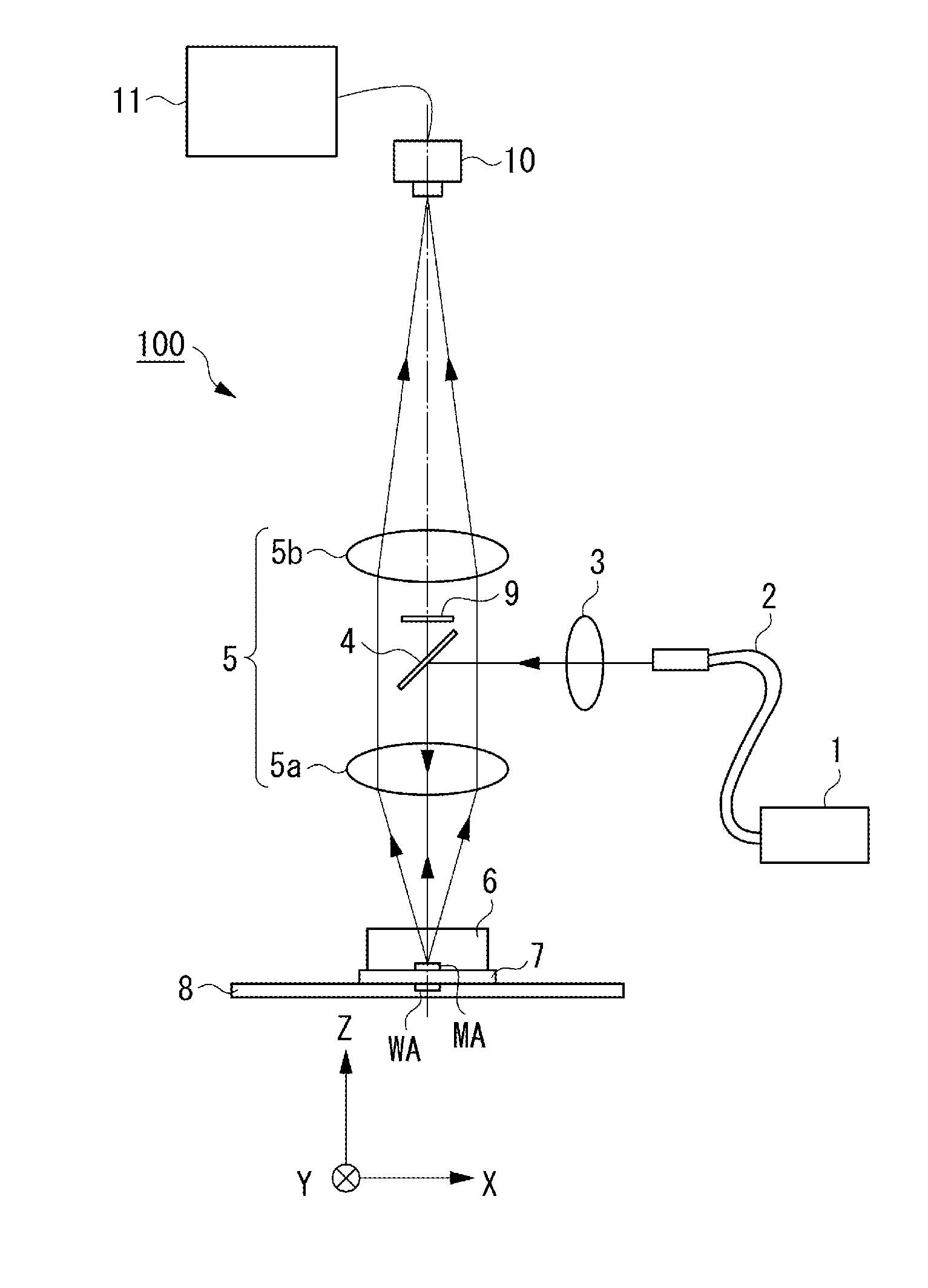
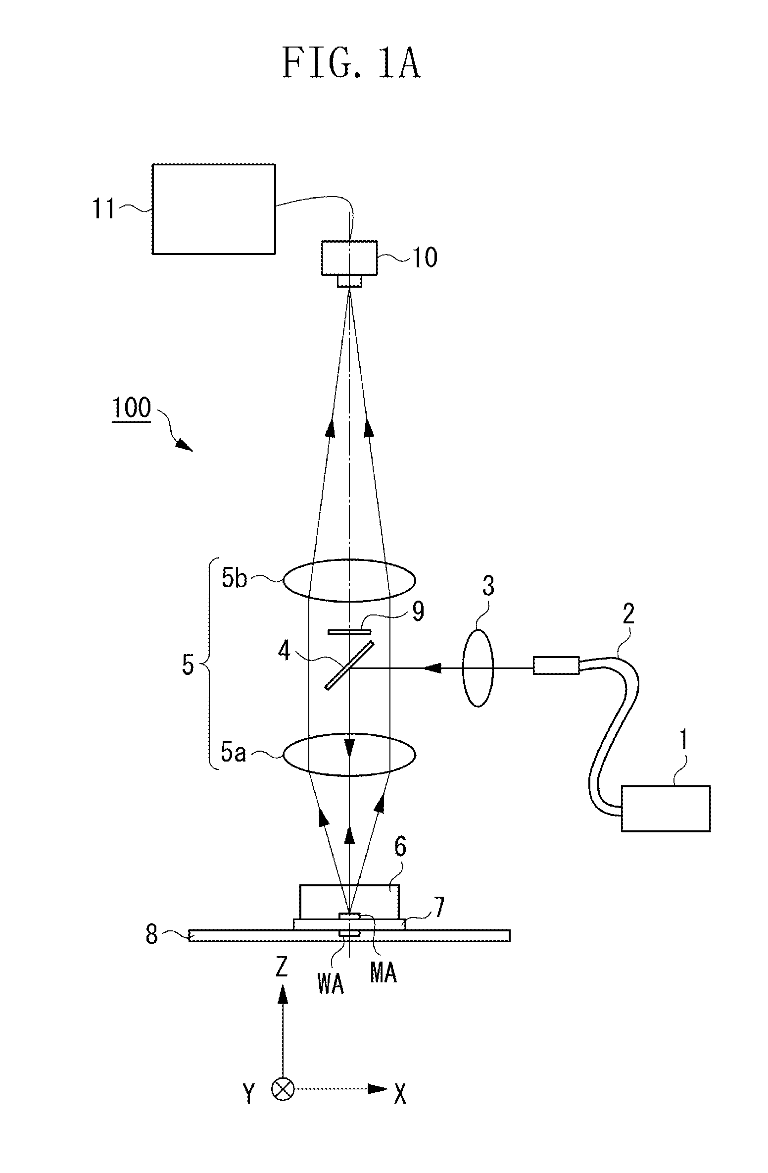
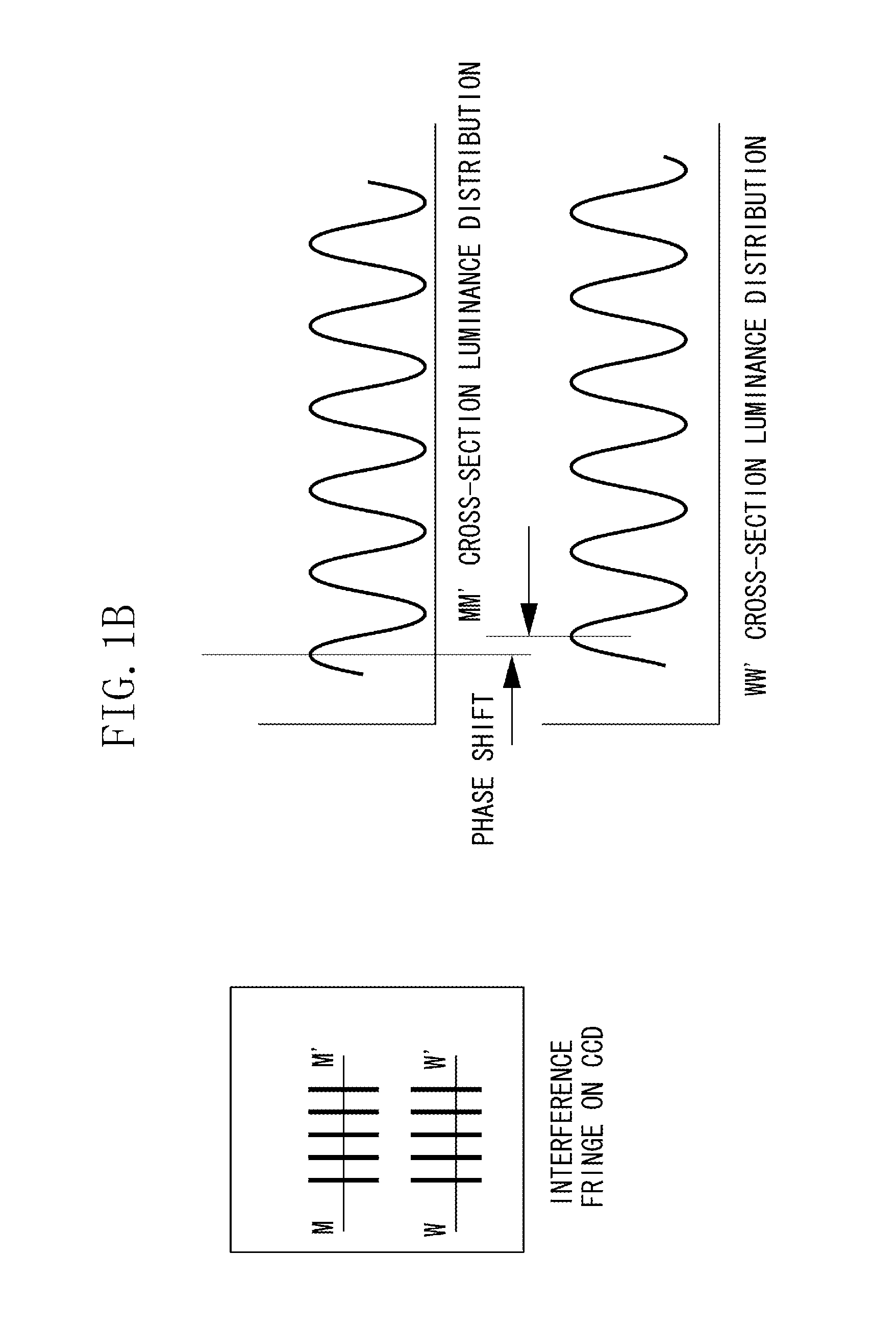
[0024]First, a first exemplary embodiment of the present invention will be described with reference to FIGS. 1A, 1B, and 1C, and FIGS. 2A, 2B, 2C, and 2D. FIGS. 1A, 1B, and 1C are diagrams illustrating a configuration of a position detection apparatus 100 according to the first exemplary embodiment and illustrate an example in which the present invention is applied to an alignment detecting device of an imprint apparatus. In the present exemplary embodiment described below, a position detection apparatus and a position detecting method that acquire a relative position by using a mold and a wafer as two different objects will be described.

[0025]The configuration of the position detection apparatus 100 will be described with reference to FIG. 1A. Light emitted from a light source 1 is guided to an illumination optical system 3 via an optical fibe...


PUM

PropertyMeasurementUnit
Interferenceaaaaaaaaaa
Phaseaaaaaaaaaa
Wavelengthaaaaaaaaaa

Abstract

A position detection apparatus that illuminates diffraction gratings formed on two objects with light from a light source and receives diffracted light from the diffraction gratings to acquire relative positions of the two objects includes: an optical system configured to cause plus n-th order diffracted light and minus n-th order diffracted light from each of the diffraction gratings to interfere with each other, where n is a natural number; a light receiving unit; and a processing unit, wherein the light receiving unit receives a two-beam interference light from each of the diffraction gratings, and wherein the processing unit acquires the relative positions of the two objects by using the two-beam interference light at an area where two-beam interference lights of the diffracted light from the respective diffraction gratings do not overlap each other among the two-beam interference lights of the diffracted light from each of the diffraction gratings.

Description

BACKGROUND OF THE INVENTION[0001]1. Field of the Invention[0002]The present invention relates to a position detection apparatus, an imprint apparatus, and a method for manufacturing a device.[0003]2. Description of the Related Art[0004]An imprint technology which is a technology that transfers a minute structure on a mold to a workpiece such as a resin or a semiconductor substrate has gained attention in recent years. The imprint technology can mass-produce semiconductor devices at low cost without needing a large-scale device such as a vacuum process, and the like.[0005]In the imprint technology, a workpiece formed by applying the resin onto a substrate in advance is prepared. As the resin, for example, a photo-curable resin or a thermosetting resin can be used. The resin on the substrate contacts a mold having a desired uneven pattern to fill the uneven pattern with the resin. The resin is cured through ultraviolet-light irradiating or heating while the resin and the mold contact ...

Claims


Application Information

Patent Timeline
IPC IPC(8): G01B11/14
CPCG03F9/7042G03F9/7049B82Y40/00G03F7/0002B82Y10/00G01B11/14H01L21/0274
Inventor MATSUMOTO, TAKAHIRO
Owner CANON KK
Learn More