
Method for performing closed-loop and/or open-loop control of a windshield wiper device, computer program product, control device and windshield wiper device

a technology of windshield wiper device and control device, which is applied in vehicle maintenance, vehicle cleaning, transportation and packaging, etc., can solve the problems of limiting the comfort of the vehicle driver, affecting the operation of causing large loads to occur, so as to prevent damage to the windshield wiper device

Active Publication Date: 2013-06-27
ROBERT BOSCH GMBH
View PDF3 Cites 0 Cited by
  • Summary
  • Abstract
  • Description
  • Claims
  • Application Information

AI Technical Summary

Benefits of technology

The present invention provides a method for operating a direct wiper drive with a motor for a wiper device that can avoid blocking of a windshield wiper device without adversely affecting the system service life to a relevant degree. The method includes making available a limiting load torque for normal operation, determining at least one characteristic variable for the plausibility of an exceptional case, and deactivating the limiting load torque as a function of the characteristic variable. The method also includes making available a further limiting load torque, wherein the further limiting load torque is greater than the limiting load torque. The method can selectively make available a boost function for a wiper system and can limit the number of trials for clearing a buildup of snow on a windshield to prevent damage to the windshield wiper device. The method can also limit the entire load spectrum over the service life of a component to ensure that a boost function occurs only with a relevant degree of frequency.

Problems solved by technology

In particular, very large loads can occur in the latter case of blocking, in particular in the case of rigid systems.
However, there are operating modes in which limiting brings about blocking of the wiper system, which at least restricts the comfort from the point of view of a vehicle driver.

Method used


Image

  • Method for performing closed-loop and/or open-loop control of a windshield wiper device, computer program product, control device and windshield wiper device
  • Method for performing closed-loop and/or open-loop control of a windshield wiper device, computer program product, control device and windshield wiper device
  • Method for performing closed-loop and/or open-loop control of a windshield wiper device, computer program product, control device and windshield wiper device

Examples


Embodiment Construction

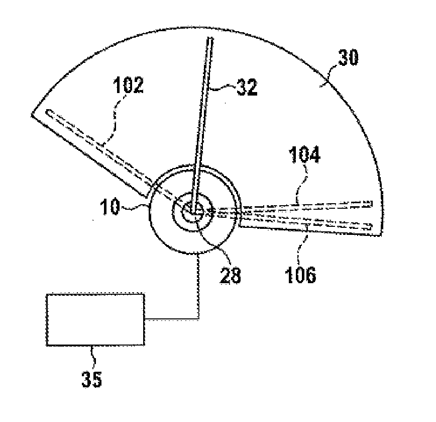
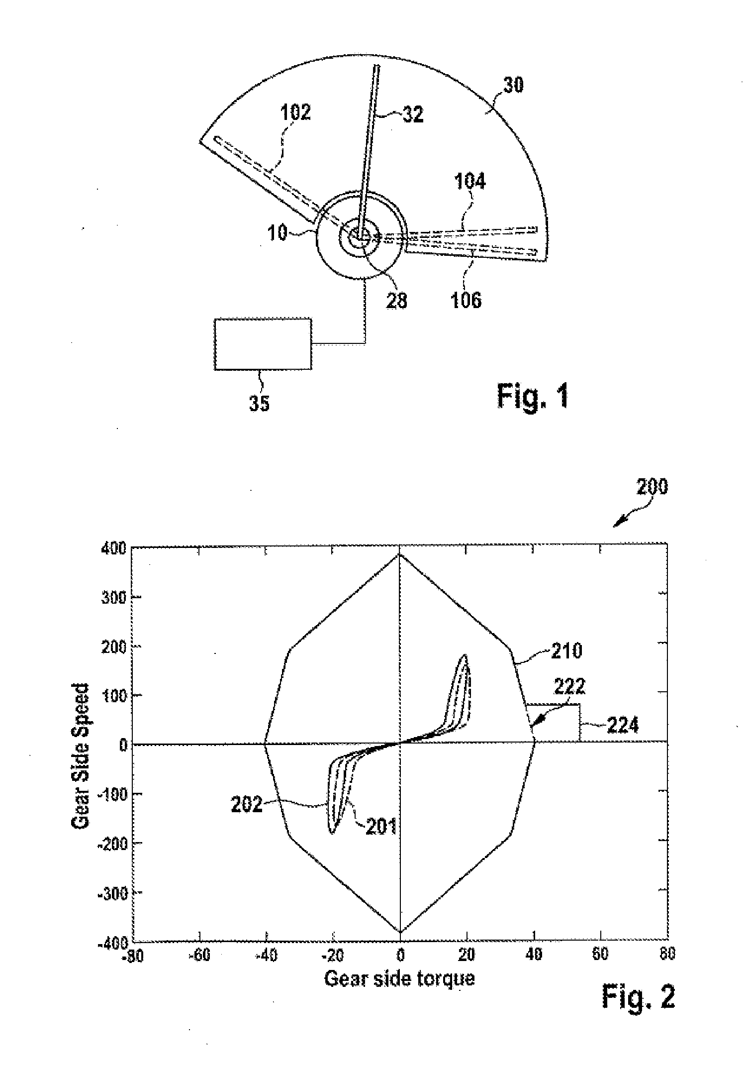
[0025]FIG. 1 shows a schematic illustration of a design of a wiper drive. A motor 10 brings about a rotational movement of the wiper lever 32 at the bearing 28. FIG. 1 shows the wiper lever 32 in a random position on the windshield 30. The upper turning position 102, the lower turning position 104 and the extended parked position 106 are illustrated by the dashed lines. By reversing rotation of the motor 10, during normal operation the wiper lever 32 is moved to and fro between the upper turning position 102 and the lower turning position 104. If the wiper is not required or not used during operation of the motor vehicle, that is to say if a user switches off the wiper drive, the wiper lever 32 moves from the lower turning position 104 into the extended parked position 106. The extended parked position 106 is typically located at a very low position on the windshield, for example entirely or partially in the wind shadow of a corresponding protrusion of a radiator hood of a motor veh...


PUM


Abstract

A method for operating a direct wiper drive having a motor, in particular for a windshield wiper, is described. The method comprises making available a limiting load torque for normal operation, determining at least a first characteristic variable for the plausibility of an exceptional case, determining at least a second characteristic variable for the reliability of an exceptional case, and deactivating the limiting load torque as a function of the first characteristic variable and the second characteristic variable.

Description

BACKGROUND OF THE INVENTION[0001]The invention relates to a method for operating a wiper drive having a motor, a computer program product with program code which is stored on a non-transient machine-readable carrier, and a control device for a wiper drive. In particular, the invention relates here to the load-dependency of the motor torque during wiping. Embodiments of the invention also relate to a windshield wiper device and to a method for performing closed-loop and / or open-loop control of a windshield wiper device, in particular for a motor vehicle having an electronically actuated wiper drive motor.[0002]Numerous methods for controlling wiper drives (WSAs) are known. For example, DE 101 44 985 describes a drive which drives a wiper via a wiper shaft and a torque which is dependent on the position of the gear mechanism. In this context, a controller is used in such a way that the torque which is output by a motor is determined at every point in time by taking into account the tr...

Claims


Application Information

Patent Timeline
Patent Type & Authority Applications(United States)
IPC IPC(8): H02P7/00
CPCH02P7/00B60S1/08
Inventor BRAUN, PETERWEGNER, NORBERTRAPP, JUERGENMAY, MICHAELKUDERER, ALEXANDER
Owner ROBERT BOSCH GMBH
Learn More