
Low-field nmr device for measuring the water content of solids and slurries

a low-field, water-content technology, applied in the direction of nmr measurement, magnetic variable regulation, instruments, etc., can solve the problems of limiting the practical dimensions and other specifications of the measurement device, limiting the wide use of the nmr-based moisture content measurement device, and reducing the cost of amplifiers. , the effect of small and cost-effectiveness

Inactive Publication Date: 2013-06-20
METSO AUTOMATION OY
View PDF5 Cites 21 Cited by
  • Summary
  • Abstract
  • Description
  • Claims
  • Application Information

AI Technical Summary

Benefits of technology

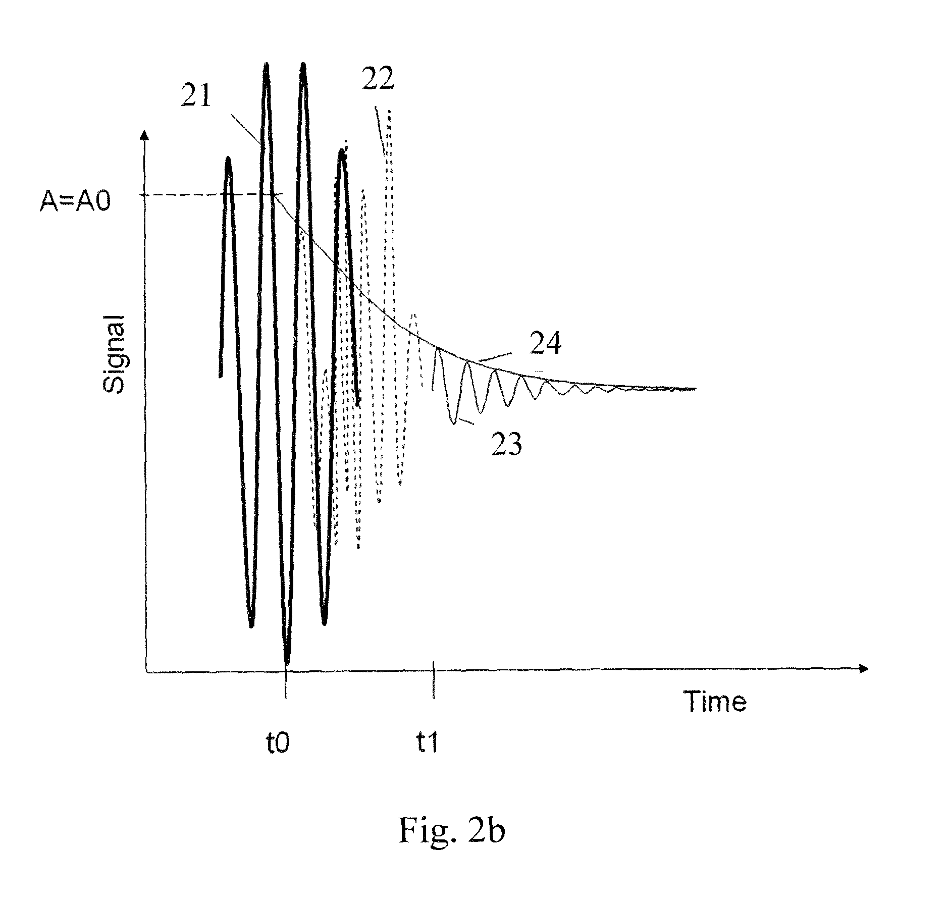
The invention is a device that measures RF signals after a certain time period to recover from the previous excitation pulse. By measuring the RF signal and estimating its value at the time of the excitation pulse, the device can determine the water content of a sample. This measurement method allows for the use of a small and cost-effective device, which was previously limited to measuring water content in larger samples. The device also uses a low main magnetic field, which has advantages compared to NMR devices based on permanent magnets or superconducting magnets. Overall, this invention provides a convenient and cost-effective way to measure water content in small samples.

Problems solved by technology

Wide usage of NMR based moisture content measurement devices has been hindered mainly by the high cost of measurement devices.
In particular, in many applications, e.g. biomass water content measurements, the desired sample volume is of the order of several deciliters or larger, which sets practical limits for device dimensions and other specifications.
However, the use of field strengths of this magnitude increases device costs, power consumption and magnet mass, for example.
In addition, the temperature variation and main field inhomogeneity effects are significant in high fields, further complicating device design.

Method used


Image

  • Low-field nmr device for measuring the water content of solids and slurries
  • Low-field nmr device for measuring the water content of solids and slurries
  • Low-field nmr device for measuring the water content of solids and slurries

Examples


Embodiment Construction

[0049]A measurement system according to one embodiment is shown in FIG. 1. The NMR unit is denoted with the reference numeral 119 and comprises a main DC electromagnet 118 and an RF coil 120 placed inside the main magnet 118. The main magnet 120 is powered by a DC power supply 126. The system also comprises a control and data acquisition computer 102. The computer 102 is connected via a control signal and data transmission channel 134 to an ADC and DAC converter 106. The RF coil 120 is connected to a directional switch 112 which is used for transmitting both the excitation signal from the ADC / DAC 106 to the RF coil 120 and the NMR signal from the RF coil 120 to the ADC / DAC 106. The excitation signal 132 is transmitted through an RF power amplifier 110 powered by a suitable power supply 108. and the NMR signal is received via input amplifiers and low pass filters 114, 116 The weight of the sample placed inside the RF coil is measured using a load cell 122 connected via a load cell am...


PUM


Abstract

A Nuclear Magnetic Resonance (NMR) apparatus and method for measuring the water content of samples has a device to produce a main magnetic field; a sample receiving space within a main magnetic field; a device to excite a measurable RF magnetization to a sample placed into the sample receiving space at an operating frequency defined by the main magnetic field; a device to measure the RF signal produced by the excited sample; and a device to determine the water content in the sample based on the RF signal. The sample receiving space is capable of accommodating a sample having a volume of at least 0.5 dm3, and the device to produce a main magnetic field has a resistive electromagnet which is adapted to produce a main magnetic field corresponding to an operating frequency of 400-2000 kHz.

Description

FIELD OF THE INVENTION [0001]The invention relates to Nuclear Magnetic Resonance (NMR) measurement devices and methods. In particular, the invention relates to a NMR device and method for measuring water content of solids and slurries.BACKGROUND OF THE INVENTION[0002]NMR measurements are based on providing a net magnetization to a large group of atomic nuclei using a static magnetic field (main field) and deflecting the net magnetization from the direction of the static magnetic field using a radio frequency pulse (RF pulse) of a radio frequency magnetic field (RF field), the operating frequency (Larmor frequency) being defined by the nuclei concerned and the magnitude of the main field. The relaxation of the deflected precessing net magnetization can be detected by measuring the NMR signal, i.e. the EMF induced in the receiving RF coils caused by the precessing net magnetization, which is gradually relaxing back to parallel with the main field (known also as Free Induction Decay, F...

Claims


Application Information

Patent Timeline
IPC IPC(8): G01R33/28G01R33/44
CPCG01N24/08G01R33/381G01R33/445G01N24/085G01R33/44G01N24/081G01N24/082G01R33/28Y02A90/30G01R33/24
Inventor VIRTANEN, SAMIVIITANEN, VELI-PEKKA
Owner METSO AUTOMATION OY
Learn More