
Electronic state calculation method, electronic state calculation device, and recording medium

Active Publication Date: 2013-06-13
OSAKA UNIV
View PDF14 Cites 2 Cited by
  • Summary
  • Abstract
  • Description
  • Claims
  • Application Information

AI Technical Summary

Benefits of technology

The patent text describes a method for improving the speed of calculating a solution by using a parallelization calculation method, which includes the density functional method. This method can efficiently attain the properties shown by the exact solution within a range of calculation resources.

Problems solved by technology

Although the calculation theory based on the density functional theory includes a self-consistent calculation theory by local density approximation (LDA), it is known that the calculation result does not always show the same properties as in experiments.
The above-mentioned approximate calculation techniques all have a problem that they do not provide a method for always attaining the properties shown by a real solution (exact solution) by a finite number of times of calculation.
That is, no self-consistent calculation theory is present that always ensures reproduction of the properties of the real solution while utilizing a high-accuracy one-electron basis provided by the LDA.
However, when the goal is limited to reproduction of only the physical or chemical properties of a material, the method that attains the exact solution by an approximation model sequence attaining the exact solution in the model space does not use the attainment of the properties of the exact solution by a smaller finite number of times of calculation.

Method used


Image

  • Electronic state calculation method, electronic state calculation device, and recording medium
  • Electronic state calculation method, electronic state calculation device, and recording medium
  • Electronic state calculation method, electronic state calculation device, and recording medium

Examples


first embodiment

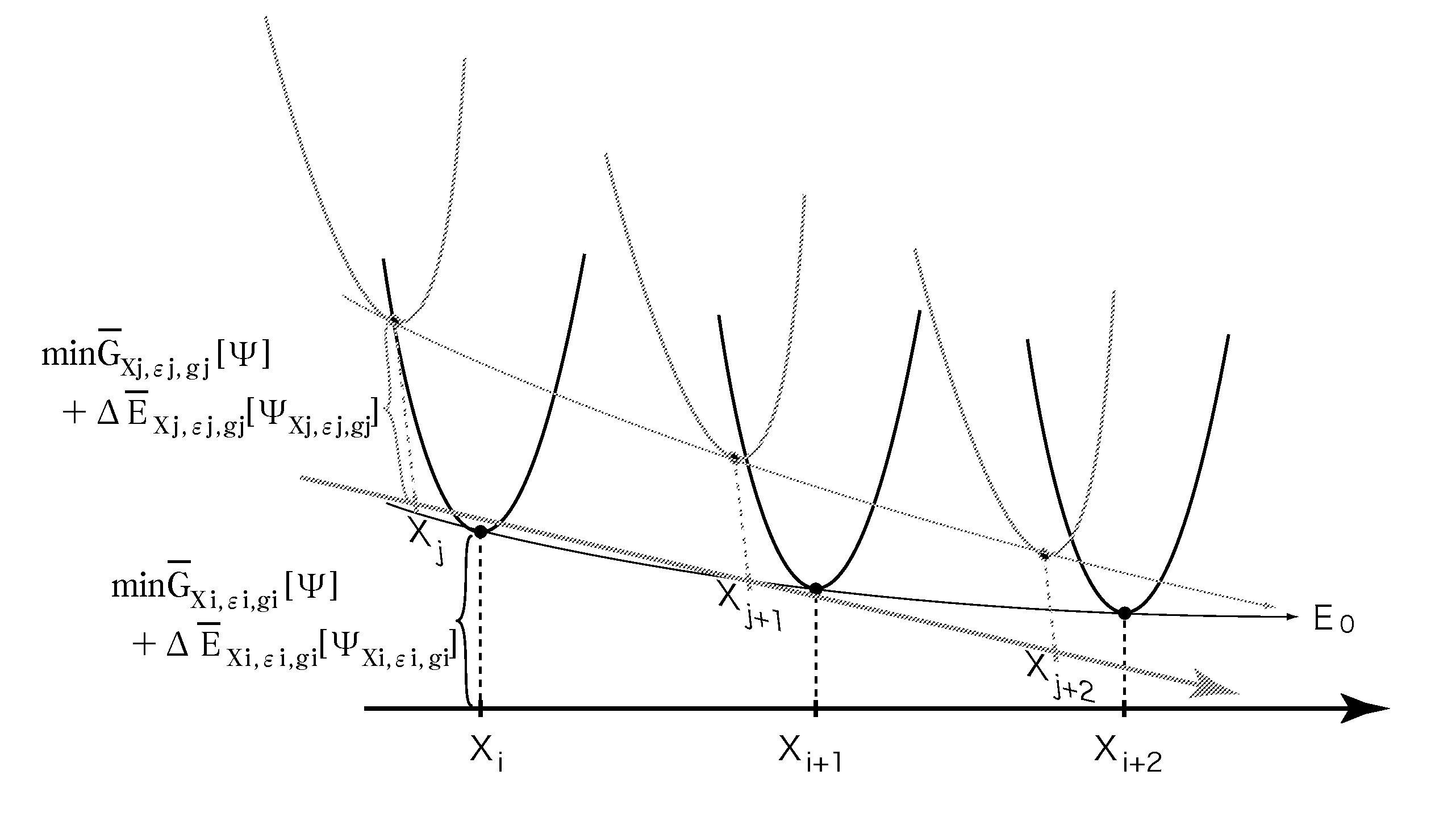
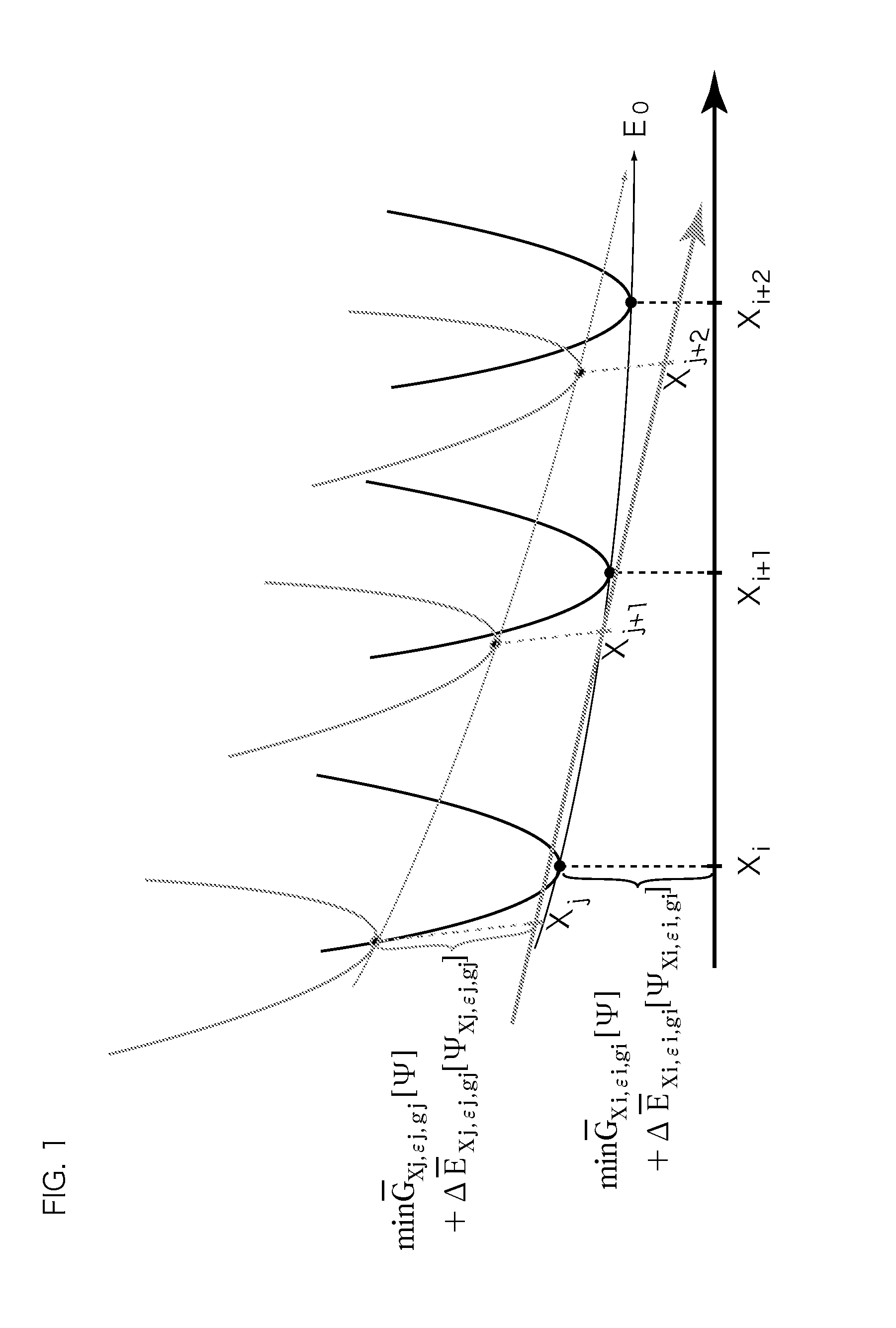
[0045]The calculation principle of an electronic state calculation method according to the present embodiment is as follows: In the present embodiment, as a method of determining an optimized operation model that realizes the properties shown by the exact solution of the electronic state, it is aimed to reproduce the properties through numerically obtaining an order parameter which is the electron density generated by a Coulomb many-body system in the ground state. The electron density is a physical quantity that can be observed by an experiment, and its existence is known. An energy E0 of the ground state of the Coulomb many-body system can be numerically evaluated since it satisfies the following expression:

E0≤mini{minΨG_Xi,ɛi,gi[Ψ]+ΔE_Xi,ɛi,gi⌊ΨXi,ɛi,gi⌋}.(Formula1)

[0046]The energy functional GbarXi, ∈i, gi is defined by the following formula:

G_Xi,ɛi,gi[Ψ]=〈ΨT^+V^redXiΨ〉+e22∫rr′nΨ(r)nΨ(r)r-r′+Eɛilocal[Ψ]+Eginon-local[Ψ]+∫rvext(r)nΨ(r).(Formula2)

[0047]Moreover, ΔEbarXi, ∈i, gi is ...

second embodiment

[0101]An up-conversion process may be introduced to the electronic state calculation method described in the first embodiment.

[0102]In the second embodiment, a form will be described in which the up-conversion process is introduced to the electronic state calculation method of the first embodiment.

[0103]The following formula 13 is a definitional equation of a model used for the second embodiment of the up-conversion method, by a model in which the projection operator is introduced to one-electron bands or one-electron orbitals for which the fluctuation effect is important, and a screened interaction type interaction strength is introduced as a parameter to adjust the strength of the effective interaction provided by the fluctuation term.

G_λ,A[Ψ]=〈ΨT^+V^(λ)Ψ〉+e22∫rr′nΨ(r)nΨ(r)r-r′+(1-λ)Erxc[nΨ]+∫rnΨ(r)vext(r),V~(λ)=λ{12∫3r3r′2r-r′:n^(r)n^(r′):-12∫3r3r′2r-r′nΨ(r)nΨ(r′)-12∫3r3r′2-κ(1-λ)r-r′r-r′ [P^A:n^(r)n^(r′):P^A-〈ΨP^An^(r)P^AΨ〉〈ΨP^An^(r′)P^AΨ〉}+12∫3r3r′2-κ(1-λ)r-r′r-r′[P^A:n^(r)n^(r...

third embodiment

[0114]By using the electronic state calculation method described in the first and second embodiments, an optimized operation model where the number of times of calculation is the smallest while the physical properties shown by the exact solution are reproduced can be determined.

[0115]In the third embodiment, a method of selection of the optimized operation model will be described.

[0116]Formula 14 shown below shows a model functional that provides a continuous model series that connects with the Coulomb system by the single continuous parameter with convexity. Vhat / tilde(λ) is provided as a correlation term that generates a positive definite operator from the λ differential. The value of λ takes a value from 0 to 1, and at λ=1, the original Coulomb interaction system is reproduced.

G_λ,A[Ψ]=〈ΨT^+V~(λ)Ψ〉+e22∫rr′nΨ(r)nΨ(r)r-r′+(1-λ)Erxc[nΨ]+∫rnΨ(r)vext(r),V~(λ)=λ{12∫3r3r′2r-r′:n^(r)n^(r′):-12∫3r3r′2r-r′nΨ(r)nΨ(r′)-12∫3r3r′2-κ(1-λ)r-r′r-r′ [:n^~(r)n^~(r′):-〈Ψn^~(r)Ψ〉〈Ψn^~(r′)Ψ〉}+12∫3r3r′...


PUM


Abstract

A method of calculating an electronic state of a material by using a calculation device, wherein the calculation device sets a set containing, as elements, a plurality of operation models, where each of operation models provides an approximate solution to the electronic state of the material, determines an optimized operation model that are close in distance in a space formed by the set while defining a direction in which the calculated self-consistent solutions of the effective Hamiltonian of an electron system continuously change, evaluates a variational energy of the electron system by the self-consistent solution, updates the operation model so that the evaluated variational energy approaches an energy of an exact solution to be calculated and further, so that the variational energy forms a monotonically decreasing convex function, and calculates the exact solution of the electronic state from one or a plurality of variational energy series.

Description

CROSS-REFERENCE TO RELATED APPLICATIONS[0001]This application is the national phase under 35 U.S.C. §371 of PCT International Application No. PCT / JP2011 / 68589 which has an International filing date of Aug. 17, 2011 and designated the United States of America.BACKGROUND[0002]1. Technical Field[0003]The present application relates to an electronic state calculation method, an electronic state calculation device and a recording medium for obtaining an electronic state of a material by a calculation.[0004]2. Description of the Related Art[0005]Conventionally, there exits a calculation theory called a first-principle calculation theory of estimating physical or chemical properties of a material (hereinafter, referred to as properties) according to a basic rule of quantum mechanics. Of this calculation theory, a calculation theory based on a density functional theory is present in which properties such as mechanical properties including elasticity, conductive properties including supercon...

Claims


Application Information

Patent Timeline
IPC IPC(8): G06F17/11G01N27/00
CPCG06F17/11G06F19/701G01N23/2251G01N27/00G16C10/00H01J2237/2445H01J2237/24485H01J2237/2516
Inventor KUSAKABE, KOICHIMARUYAMA, ISAO
Owner OSAKA UNIV
Learn More