Magnetic disk apparatus, method of controlling a magnetic disk, and program for controlling a magnetic disk

Inactive Publication Date: 2006-01-05
KK TOSHIBA
View PDF18 Cites 0 Cited by
  • Summary
  • Abstract
  • Description
  • Claims
  • Application Information

AI Technical Summary

Benefits of technology

[0010] The present invention has been made to solve the problems described above. An object of this invention is to provide a magnetic disk apparatus, a method of controlling a magnetic disk and a program for controlling a magnetic disk, which can avoid data-writing on an adjacent track in spite of disturbance such as vibration and which can prevent a decrease in the data-writing performance.
[0033] In the present invention, if the head acceleration is high, the next head position is calculated in consideration of the head acceleration. This reduces the risk that the head writes data on a track adjacent to the target track. If the head acceleration is low, the next head position is calculated from the present head position and the head speed. The speed of calculation therefore increases to cope with any abrupt changes. Further, the write-prohibiting slice is broadened while the data-writing is prohibited, and the data-writing is permitted if the head position falls within the broad write-prohibiting slice. Thus, the data-writing efficiency will not excessively decrease in spite of the write-prohibiting period. Moreover, the servo band is increased and the other parameters are changed, in any retry operation. This helps to avoid data-writing on an adjacent track, in spite of vibration.

Problems solved by technology

Further, the data-writing performance is extremely low, because no data is written until a prescribed condition is satisfied, once data-writing unit 6 has received a write-prohibition signal.
Furthermore, if the heads 2 and 9 vibrate and the head-drive control unit 7 therefore performs an retry operation, no measures cannot be taken to compensate the vibration during the retry operation.

Method used


Image

  • Magnetic disk apparatus, method of controlling a magnetic disk, and program for controlling a magnetic disk
  • Magnetic disk apparatus, method of controlling a magnetic disk, and program for controlling a magnetic disk
  • Magnetic disk apparatus, method of controlling a magnetic disk, and program for controlling a magnetic disk

Examples


Embodiment Construction

[0039] An embodiment of the present invention will be described, with reference to the accompanying drawings.

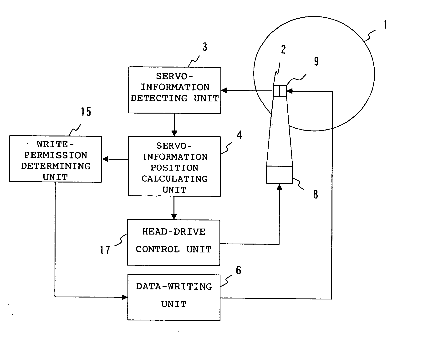
[0040] A magnetic disk apparatus that is an embodiment of the present invention will be described. FIG. 1 is a block diagram showing the configuration of the magnetic disk apparatus according to this embodiment. The components that are identical or equivalent to those shown in FIG. 5 are designated at the same reference numerals in FIG. 1 and will not be described in detail. The magnetic disk apparatus of FIG. 1 differs from the configuration of FIG. 5 in that a write-permission determining unit 15 and a head-drive control unit 17 are provided in place of the write-permission determining unit 5 and the head-drive control unit 7, respectively.

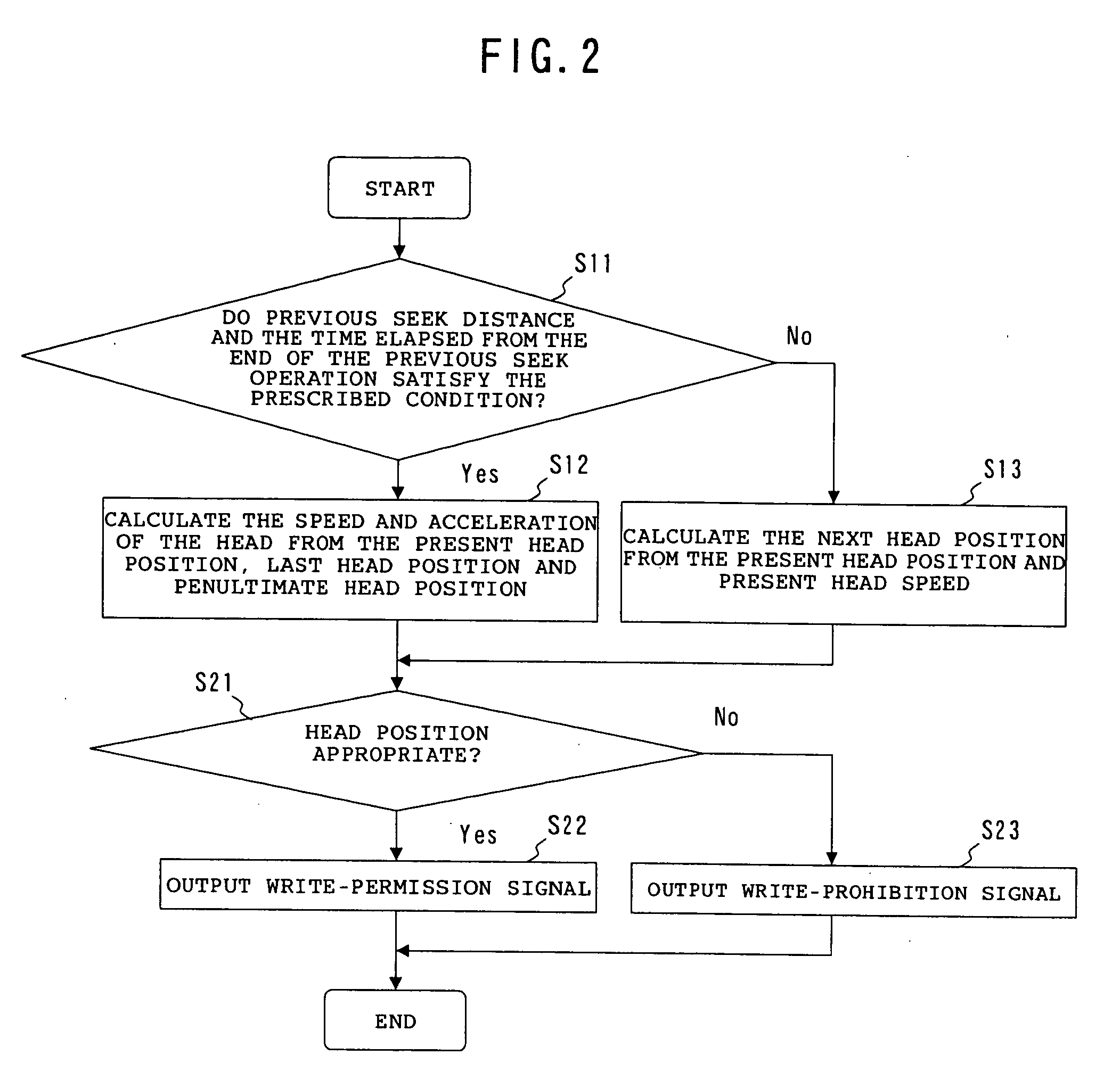
[0041] It will be explained how the write-permission determining unit 15 performs its function. FIG. 2 is a flowchart explaining how the unit 15 determines whether a data-writing operation is permitted or not. First, the write-permissio...


PUM


Abstract

A magnetic disk apparatus comprising a magnetic disk 1, a head, a servo-information detecting unit 3, a servo-information position calculating unit 4, a write-permission determining unit 15, a data-writing unit 6, and a head-drive control unit 17. Servo information and data are recorded on the disk 1. The head reads and writes data from and on the magnetic disk 1. The servo-information detecting unit 3 detects a present head position from a signal supplied from the head. The write-permission determining unit 15 calculates a present head speed and a present head acceleration from the present head position and a previous head position detected in the past, and determines whether data can be written, from the present head position, the present head speed and the present head acceleration. The data-writing unit 6 writes data in accordance with a decision made by the write-permission determining unit 15. The head-drive control unit 17 drives the head in accordance with the present head position.

Description

BACKGROUND OF THE INVENTION [0001] 1. Field of the Invention [0002] The present invention relates to a magnetic disk apparatus, a method of controlling a magnetic disk, and a program for controlling a magnetic disk, all designed to enhance the efficiency of writing data on a magnetic disk. [0003] 2. Description of the Related Art [0004] First, a conventional magnetic disk apparatus will be described. FIG. 5 is a block diagram illustrating the configuration of the conventional magnetic disk apparatus. As FIG. 5 shows, this magnetic disk apparatus comprises a magnetic disk 1, a read head 2, a servo-information detecting unit 3, a servo-information position calculating unit 4, a write-permission determining unit 5, a head-drive control unit 7, a data-writing unit 6, an actuator 8 and a write head 9. [0005] Servo information and data are recorded on the magnetic disk 1. Located above the magnetic disk 1, the read head 2 reads signals from the disk 1. The signals are output to the servo-...

Claims


Application Information

Patent Timeline
IPC IPC(8): G11B19/04G11B5/596
CPCG11B5/59633G11B5/59605
Inventor HARA, TAKESHI
Owner KK TOSHIBA
Why Eureka
Try Eureka