
Dynamic Microphone Unit and Dynamic Microphone

a dynamic microphone and microphone technology, applied in the direction of piezoelectric/electrostrictive transducers, microphone structural associations, transducer types, etc., can solve problems such as vibration of the microphone unit, and achieve the effect of reducing noise and reducing vibration

Inactive Publication Date: 2013-06-13
AUDIO-TECHNICA
View PDF3 Cites 6 Cited by
  • Summary
  • Abstract
  • Description
  • Claims
  • Application Information

AI Technical Summary

Benefits of technology

The patent text describes a technology to reduce noise caused by mechanical vibrations, which uses a magnet and detecting coil to pick up vibrations. The technology is used in a dynamic microphone. Its technical effect is to improve the quality of sound recording by eliminating noise caused by vibration.

Problems solved by technology

The microphone case receives unnecessary external vibration to cause vibration of the microphone unit due to its inertia force relative to the microphone case.

Method used


Image

  • Dynamic Microphone Unit and Dynamic Microphone
  • Dynamic Microphone Unit and Dynamic Microphone
  • Dynamic Microphone Unit and Dynamic Microphone

Examples


embodiment 1

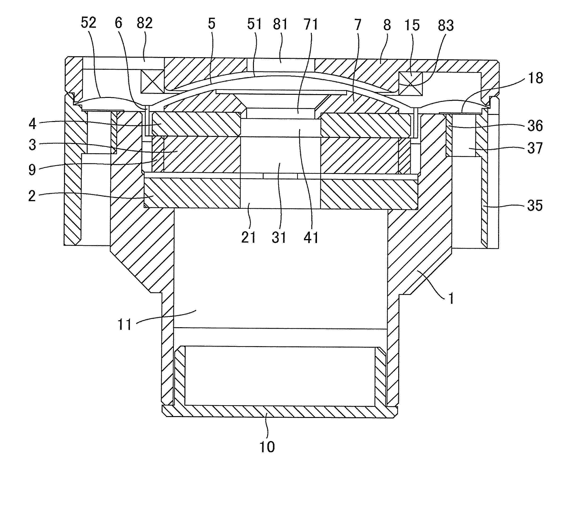
[0036]FIG. 1 illustrates a unit frame 1 serving as a base of a microphone unit. The unit frame 1 also functions as a part of a magnetic circuit, i.e., an outer yoke. The cylindrical or substantially cylindrical unit frame 1 is composed of magnetic material. As illustrated in FIG. 1, the unit frame 1 has a center hole having a smaller diameter in its substantially lower half and a step portion in its middle in the vertical direction.

[0037]In the center hole of the unit frame 1, a disk inner yoke 2 is fixed to the step portion. A disk magnet 3 is fixed above the inner yoke 2. A disk pole piece 4 is fixed above the magnet 3. The inner yoke 2, the magnet 3, and the pole piece 4 have center holes 21, 31, and 41, respectively, having the same diameter. The unit frame 1, the inner yoke 2, the magnet 3, and the pole piece 4 are bonded to each other. In this configuration, the outer circumferential surface of the inner yoke 2 is in close contact with the inner circumferential surface of the ...

embodiment 2

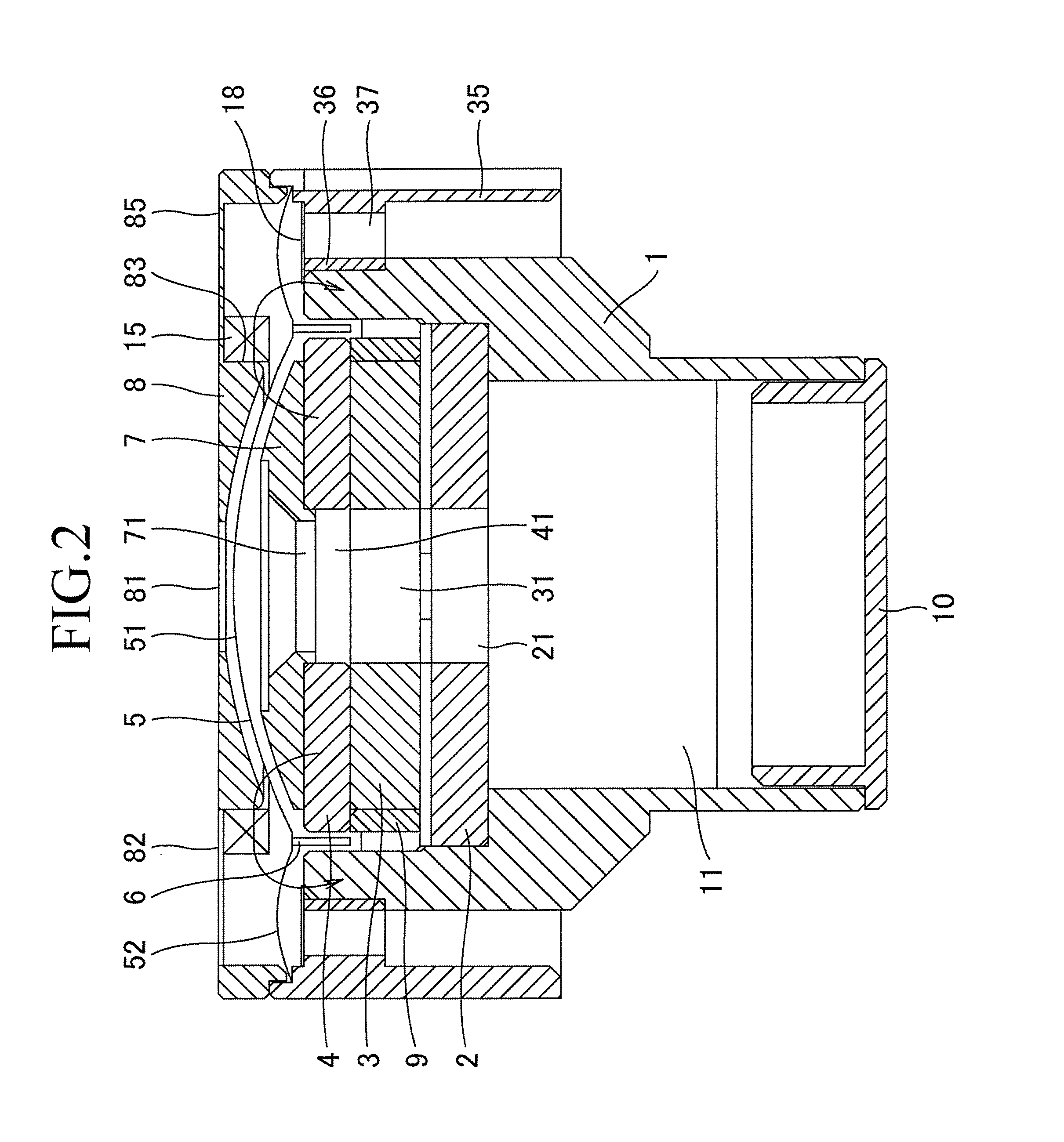
[0050]A dynamic microphone unit according to a second embodiment of the present invention will now be described. This embodiment can cancel not only hum noise but also noise caused by external mechanical vibration. The description of the second embodiment will focus on different points from the first embodiment.

[0051]In FIG. 2, the inner circumferential surface of the noise canceling coil 15 is fit along the outer circumferential surface of the convex surface 83 defined by the cylindrical surface of the resonator 8. This configuration is the same as that of the first embodiment. The resonator 8 has a thin plate connecting portion 85 between its outer circumference and the convex surface 83. According to this configuration, the connecting portion 85 can have resilience so as to vibrate due to vibration applied from the exterior. The noise canceling coil 15 is attached at a position similar to the first embodiment, i.e., at a position so as to face the voice coil 6 across the diaphrag...


PUM


Abstract

A dynamic microphone unit includes: a diaphragm that vibrates in response to received sound waves; a voice coil that is fixed to the diaphragm and vibrates together with the diaphragm; a magnetic circuit that generates a magnetic field in a magnetic gap, the voice coil being disposed in the magnetic gap; a resonator that is disposed adjacent to the obverse of the diaphragm; and a noise canceling coil that is fixed to a surface of the resonator so as to face a position of fixing the voice coil, the surface facing the diaphragm. The noise canceling coil is connected in series with the voice coil and has a winding direction different from that of the voice coil.

Description

TECHNICAL FIELD[0001]The present invention relates to a dynamic microphone unit and a dynamic microphone including a coil for reducing noise.BACKGROUND ART[0002]In a dynamic microphone, a voice coil fixed to a diaphragm is disposed in a magnetic gap defined by magnetic circuit components. In the dynamic microphone, the voice coil vibrates together with the diaphragm in the magnetic gap in response to received sound waves to generate audio signals in response to the vibration velocity due to electromagnetic conversion between the voice coil and a magnetic field. The voice coil then outputs the audio signals. At this time, if the magnetic circuit is affected by some external factor to vary a magnetic flux in the magnetic gap, the voice coil generates signals independent of sound waves. The signals independent of sound waves are noise.[0003]A factor generating noise in the dynamic microphone is, for example, an alternating magnetic field applied to the magnetic circuit. When the altern...

Claims


Application Information

Patent Timeline
Patent Type & Authority Applications(United States)
IPC IPC(8): H04R19/04H04R1/04
CPCH04R19/04H04R1/04H04R2410/03H04R9/08H04R9/046
Inventor AKINO, HIROSHI
Owner AUDIO-TECHNICA
Learn More