
Serial Lighting Interface With Embedded Feedback

a technology of embedded feedback and lighting interface, which is applied in the direction of static indicating devices, instruments, semiconductor lamp usage, etc., can solve the problems of even more complex voltage feedback requirements, color temperature of white leds varies with current, and even more complex balancing current, etc., to achieve easy partitioning and flexibility. scalability

Active Publication Date: 2013-06-13
ADVANCED ANALOGIC TECHNOLOGIES INCORPORATED
View PDF6 Cites 17 Cited by
  • Summary
  • Abstract
  • Description
  • Claims
  • Application Information

AI Technical Summary

Benefits of technology

The patent describes a new system for controlling LED strings in a display. The system has a central control unit that can communicate with different modules that provide power to the strings. The control unit uses a unique address system to identify which string of LEDs should be powered by each module. This saves space and reduces costs compared to previous systems. The control unit can also easily adjust the power supply for different strings of LEDs based on their requirements. The system is flexible and scalable, which makes it easier to create and modify custom displays.

Problems solved by technology

In the case of ROB backlighting, the voltage feedback requirement is even more complex because red, green and blue LEDs have significantly different forward voltages and cannot share a common power supply rail.
Another complication is that the color temperature of white LEDs varies with current.
In the case of ROB backlighting, balancing current is even more complex, since the luminosity, i.e. the light output or brightness, of red, blue and green LEDs differs substantially.
For example, early attempts to integrate LED driver control circuitry with multiple channels of high-voltage current sink transistors were problematic because a mismatch in the forward-voltage of the LED strings resulted in excessive power dissipation and overheating.
Attempts to minimize power dissipation by lowering LED currents and limiting the number of LEDs in a string (for better channel-to-channel voltage matching) proved uneconomical, requiring more LEDs and a greater number of channels of LED drive.
As a result, the fully integrated approach to LED backlight drive has been limited to small display panels or very expensive “high-end” HDTV's.
Forward converters and Cuk converters, while applicable, are generally too expensive and unnecessarily complex to serve the cost-sensitive display and TV markets.
If the feedback signal is incorrect, the LED supply voltage +VLED may be too high or too low.
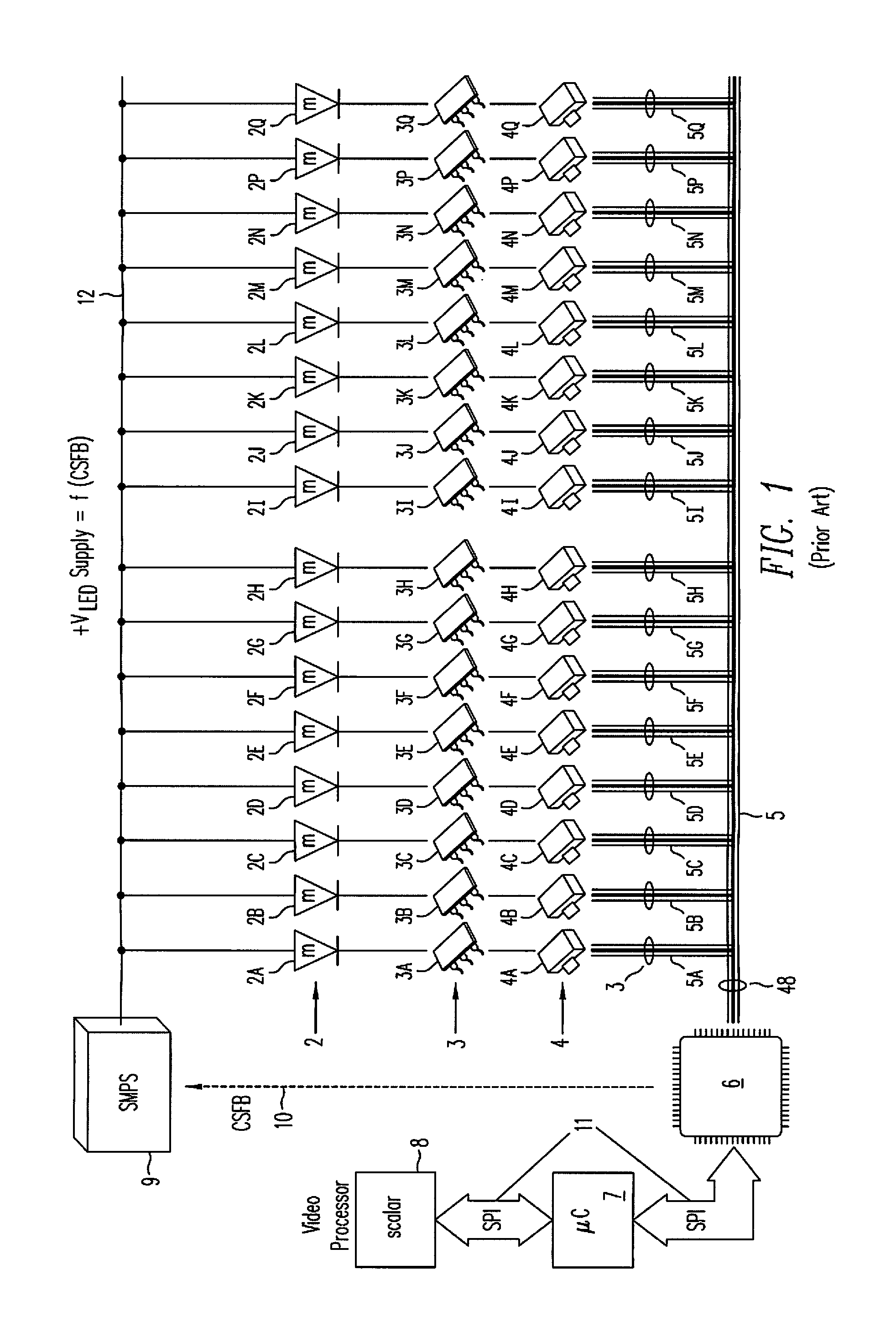
To implement the CSFB function, accurate monitoring of a LED string's forward-voltage requires electrical access to the drain of the current sink DMOSFETs 4A-4Q, which for multichip implementations can be particularly problematic, resulting in additional package pins and added component cost.
The solution is complex and expensive.
In some cases, it is desirable to split LED power into more than one power supply, e.g. to reduce the power dissipation in any one supply and its components, but prior art LED interface ICs cannot support multiple independent feedback signals.
In the case of RGB backlit displays, the solution is even more complex and expensive.
Since existing and prior art LED drivers and controllers include only a single CSFB signal per integrated circuit, independently regulating three different power supplies requires three separate LED interface ICs along with three separate power supplies, making today's RGB backlighting solutions prohibitively expensive.
In either case, the assembly of a large number of discrete components, i.e. a high build of materials (BOM) count, results in expensive PCB assembly, further exacerbated by the high package cost of high pin count package 6.
With only one CSFB signal, it is not possible to power the LEDs from more than one power supply, i.e. to split the power requirements in two to reduce the size, cost and heating in the SMPS.
Including the SPI bus interface, analog functions, power supplies and more, a costly 64 or 72-pin package is necessary.
Worse yet, many TV printed circuit board assembly houses are incapable of soldering packages with a pin pitch any smaller than 0.8 or 1.27 mm.
One significant issue with the multichip structure shown in FIG. 1 is that temperature sensing circuitry in interface IC 6 can only detect the temperature of the interface IC itself, where no significant power dissipation is occurring.
Unfortunately, the significant heat is being generated in discrete current sink DMOSFETs 4, where no temperature sensing is possible.
In summary, today's implementations for LED backlighting of LCD panels with local dimming capability suffer from numerous fundamental limitations in cost, performance, features, and safety.
Highly integrated LED driver solutions require expensive large area dice packaged in expensive high pin count packages, and concentrate heat into a single package, limiting the driver to lower currents, due to power dissipation resulting from the linear operation of the current sink MOSFETs, and lower voltages, due to power dissipation resulting from LED forward-voltage mismatch, exacerbated for greater numbers of series connected LEDs.
Moreover, discrete MOSFETs offer no thermal sensing or protection against overheating.
With only one feedback signal, these LED drivers cannot power two or more LED power supplies without including additional interface ICs, adding cost and complexity.

Method used


Image

  • Serial Lighting Interface With Embedded Feedback
  • Serial Lighting Interface With Embedded Feedback
  • Serial Lighting Interface With Embedded Feedback

Examples


Embodiment Construction

[0071]As described in the background section, existing backlight solutions for TVs and large screen LCDs are complex, expensive and inflexible. To reduce the cost of backlight systems for LCD's with local dimming without sacrificing safe and reliable operation clearly requires a completely new architecture that in the very least eliminates discrete MOSFETs, minimizes the concentration of heat within any component, facilitates over-temperature detection and thermal protection, and protects low voltage components from high voltages. While meeting these objectives may alone be insufficient to achieve a truly cost-effective solution able to meet the demanding cost targets of the home consumer electronics market, such an improvement is a necessary first step toward such a goal toward realizing low-cost local dimming.

[0072]This invention described herein enables a new cost-efficient and scalable architecture for realizing safe and economically viable LED backlighting systems for large-scr...


PUM


Abstract

A system for controlling multiple strings of LEDs includes a group of LED driver IC's, each of which includes a current sense feedback (CSFB) sample latch for storing a digital representation of the forward-voltage drop across a controlled LED string. Each CSFB latch is coupled to a register within a serial lighting interface (SLI) bus that both originates and terminates at an interface IC. As the data on the SLI bus is shifted into the interface IC, the interface IC selects the CSFB word that represents the highest forward-voltage drop of any of the controlled LED strings, which is then used by the interface IC to generate a CSFB signal for setting the appropriate supply voltage for the controlled LED strings.

Description

CROSS-REFERENCE TO RELATED APPLICATIONS[0001]This application claims the priority of Provisional Application No. 61 / 568,545, filed Dec. 8, 2011, which is incorporated herein by reference in its entirety.[0002]This application is related to the following applications, each of which is incorporated herein by reference in its entirety: application Ser. No. 13 / 346,625, filed Jan. 9, 2012 entitled Low Cost LED Driver with Integral Dimming Capability; application Ser. No. 13 / 346,647, filed Jan. 9, 2012, entitled. Low Cost LED Driver with Improved Serial Bus.BACKGROUND OF THE INVENTION[0003]This invention relates to semiconductor devices and circuits and methods for driving LEDs in lighting and display applications.[0004]LEDs are increasingly being used to replace lamps and bulbs in lighting applications including providing white light as a backlight in color liquid crystal displays (LCD) and high definition televisions (HDTV). To backlight a color LCD panel, the LED strings may comprise w...

Claims


Application Information

Patent Timeline
Patent Type & Authority Applications(United States)
IPC IPC(8): H05B37/00H05B44/00
CPCH05B33/086H05B33/0827H05B45/37H05B45/20H05B45/46H05B45/325H05B45/3725H05B45/397H05B47/165H05B47/28Y02B20/30G09G3/12H05B45/48H05B47/18
Inventor WILLIAMS, RICHARD K.D'ANGELO, KEVINBROWN, DAVID A.
Owner ADVANCED ANALOGIC TECHNOLOGIES INCORPORATED
Learn More