
Casing hanger lockdown with conical lockdown ring

Inactive Publication Date: 2013-06-13
VETCO GRAY
View PDF8 Cites 21 Cited by
  • Summary
  • Abstract
  • Description
  • Claims
  • Application Information

AI Technical Summary

Benefits of technology

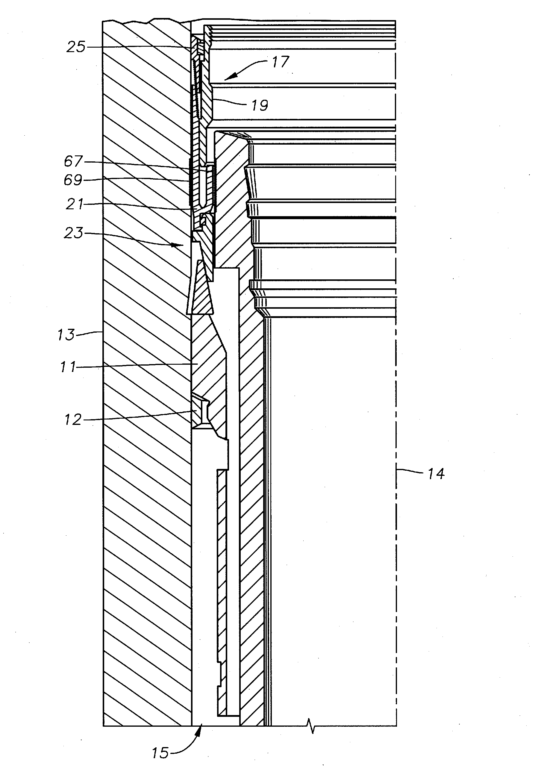
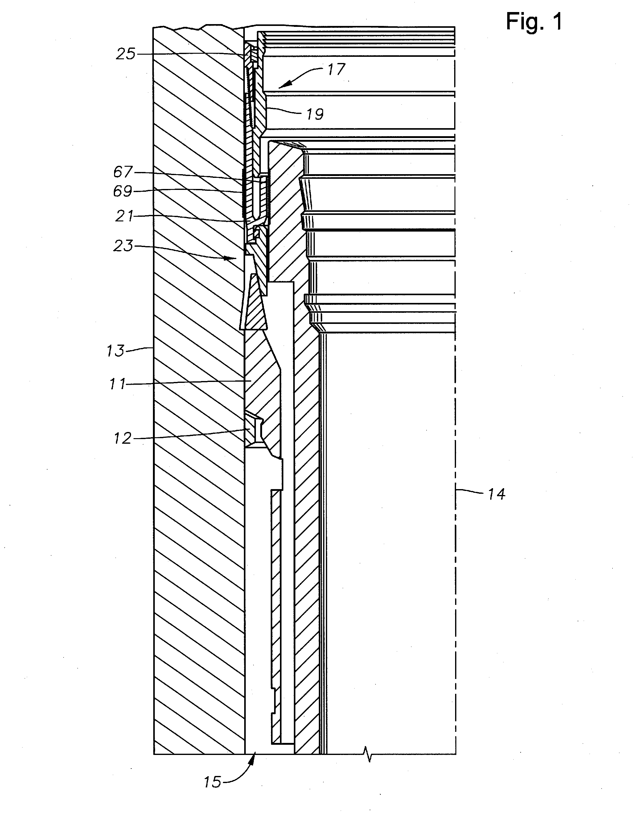
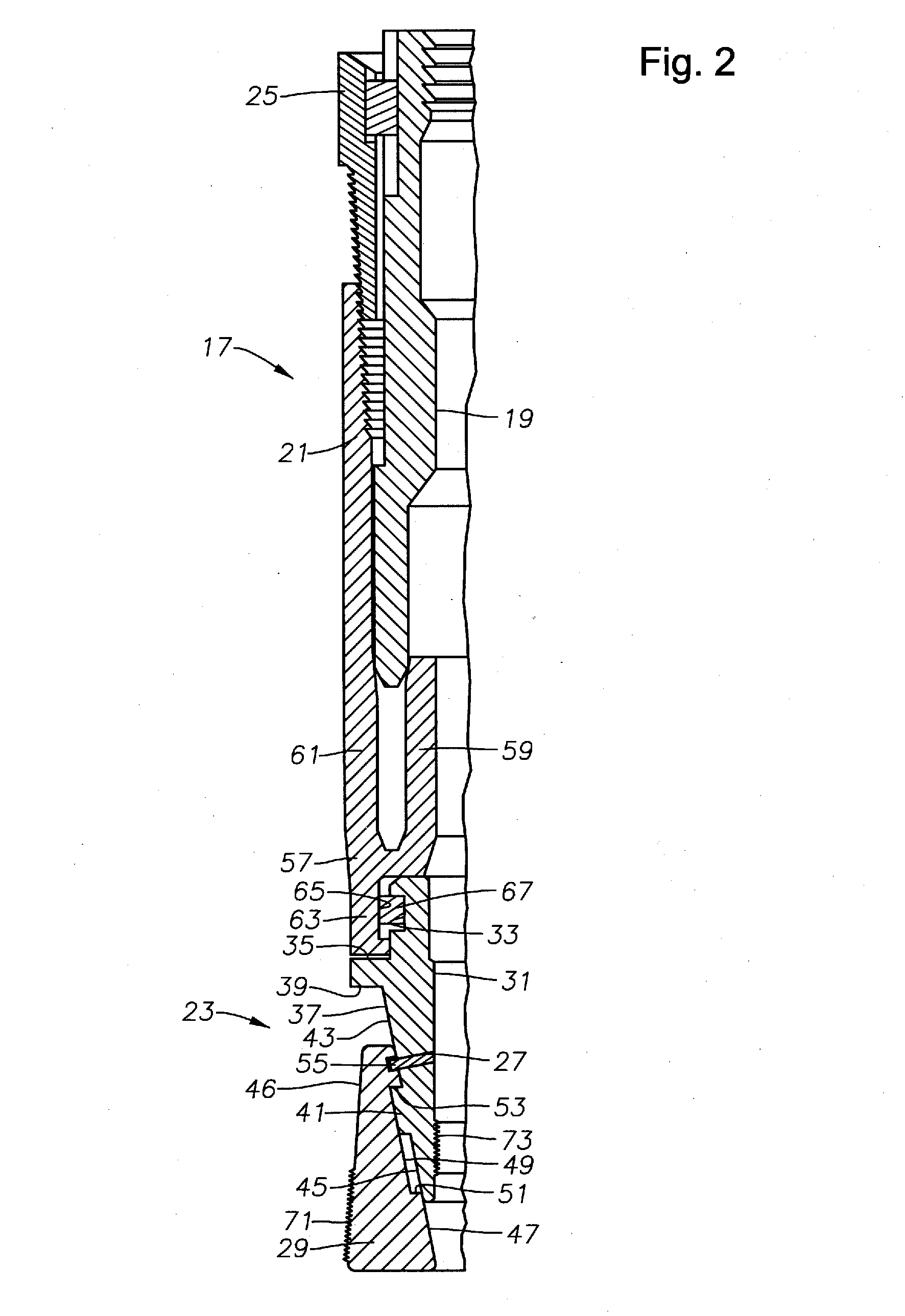
The present invention provides a wellhead assembly with a lockdown seal that prevents axial movement of the casing hanger caused by high pressures and thermal expansion. The seal is achieved through a conical profile in the wellhead member and a conical surface in the nose ring that engages with the bore of the wellhead member and the casing hanger. The lockdown seal can still engage even if the seal fails to land at the appropriate location or is prevented by debris. The disclosed embodiments offer a more efficient and reliable wellhead assembly for oil and gas wells.

Problems solved by technology

A reduction in axial force on the energizing ring results in a reduction in the radial inward and outward forces on the inner and outer walls of the seal ring, which may cause the seal to leak.
A loss of radial loading between the seal and its mating surfaces due to thermal transients may also cause the seal to leak.
Unfortunately, the groove often fills with debris prior to run-in of the lockdown seal.
The debris prevents engagement of the ring and thus, provides no lockdown benefits of the lockdown seal result.
Lockdown seals require a significant increase in production costs.
This is due in part to increased costs to modify the basic wellhead or landing sub to include the lock ring groove.
In addition, the use of these devices necessitate use of specialized tools and other components to properly land and engage the lockdown seal.
Furthermore, prior art lockdown seals require some clearance between the landing sub and the lockdown apparatus of the lockdown seal.
In such instances, the landing sub may shift axially and cause the seal to fail.

Method used


Image

  • Casing hanger lockdown with conical lockdown ring
  • Casing hanger lockdown with conical lockdown ring
  • Casing hanger lockdown with conical lockdown ring

Examples


Embodiment Construction

[0020]The present invention will now be described more fully hereinafter with reference to the accompanying drawings which illustrate embodiments of the invention. This invention may, however, be embodied in many different forms and should not be construed as limited to the illustrated embodiments set forth herein. Rather, these embodiments are provided so that this disclosure will be thorough and complete, and will fully convey the scope of the invention to those skilled in the art. Like numbers refer to like elements throughout, and the prime notation, if used, indicates similar elements in alternative embodiments.

[0021]In the following discussion, numerous specific details are set forth to provide a thorough understanding of the present invention. However, it will be obvious to those skilled in the art that the present invention may be practiced without such specific details. Additionally, for the most part, details concerning well drilling, running operations, and the like have ...


PUM


Abstract

A seal seals an annulus in a subsea assembly between a wellhead and a casing hanger landed on a shoulder within a bore of the wellhead. The seal includes a casing hanger seal ring disposed within the annulus. The seal ring engaged with an inner diameter surface of the wellhead, and engaged with an outer diameter surface of the casing hanger so that the seal ring prevents flow through the annulus. A nose ring is secured to a lower end of the seal ring so that, when the seal ring is energized, a conical surface of the nose ring engages a mating conical profile formed in the inner diameter surface portion of the wellhead and the nose ring engages a surface opposite the conical surface with a substantially smooth outer diameter surface portion of the casing hanger to limit upwards axial movement of the casing hanger.

Description

BACKGROUND OF THE INVENTION[0001]1. Field of the Invention[0002]The present invention relates in general to wellhead casing hangers and, in particular, to a casing hanger lockdown slip ring that converts axial loads into radial loads.[0003]2. Brief Description of Related Art[0004]Seals are used between inner and outer wellhead tubular members to contain internal well pressure. The inner wellhead member may be a tubing hanger that supports a string of tubing extending into the well for the flow of production fluid. The tubing hanger lands in an outer wellhead member, which may be a wellhead housing, a Christmas tree, or a tubing head. A seal or packoff seals between the tubing hanger and the outer wellhead member. Alternately, the inner wellhead member might be a casing hanger located in a wellhead housing and secured to a string of casing extending into the well. A seal or packoff seals between the casing hanger and the wellhead housing.[0005]A variety of seals of this nature have b...

Claims


Application Information

Patent Timeline
IPC IPC(8): E21B23/00E21B33/035E21B43/10
CPCE21B33/0422E21B33/04E21B33/03
Inventor YATES, CHAD ERICFORD, DAVID L.BENSON, DANIEL CALEB
Owner VETCO GRAY
Learn More