Image-capturing touch panel
a touch panel and touch screen technology, applied in the field of image capture touch panel, can solve the problems of printing paper image cannot be captured by the camera, inability to capture the image, etc., and achieve the effects of reducing the scanning bar of the conventional laptop, reducing the size of the scanning bar, and increasing the economic valu
- Summary
- Abstract
- Description
- Claims
- Application Information
AI Technical Summary
Benefits of technology
Problems solved by technology
Method used
Image
Examples
example 1
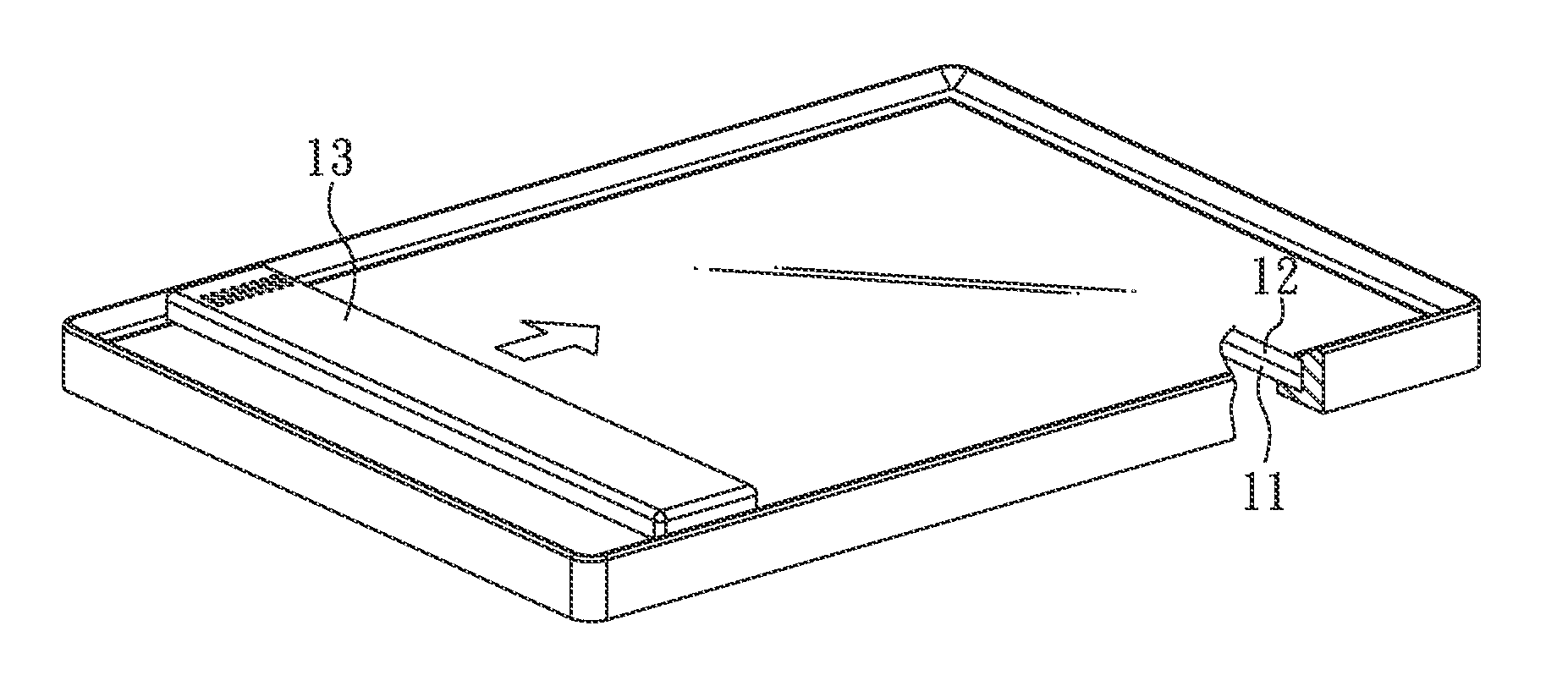
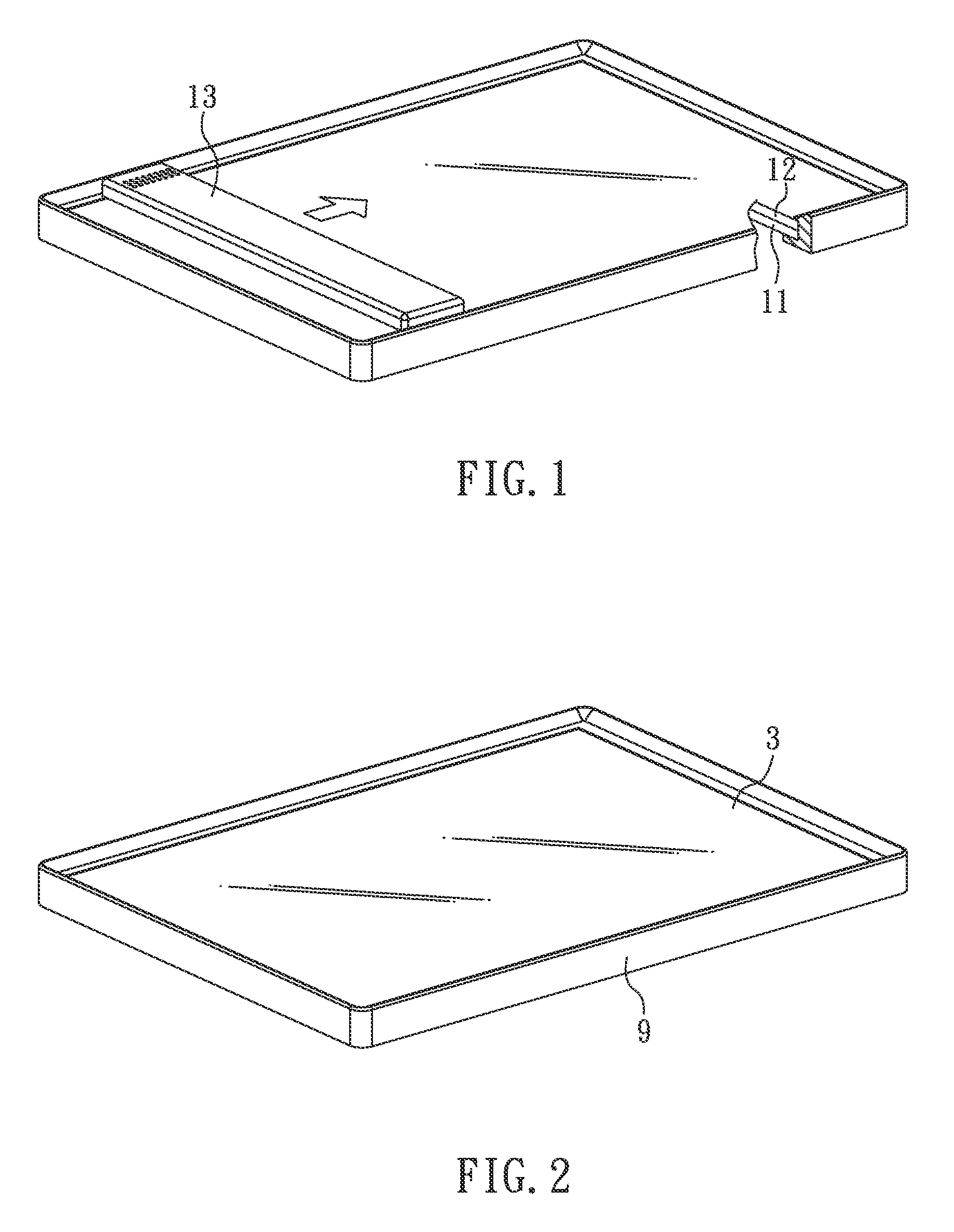
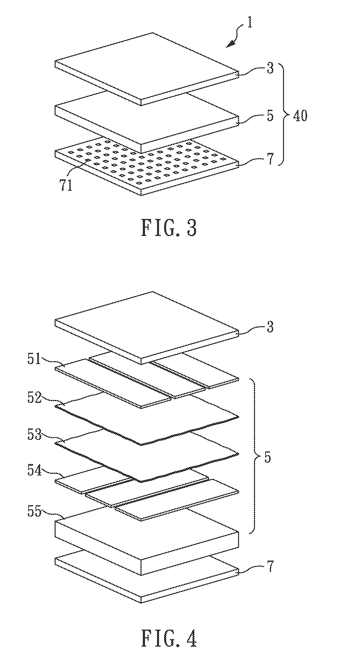
[0036]FIG. 2 shows a perspective view of an image-capturing touch panel of the present example, and FIGS. 3 and 4 are schematic diagrams showing the stack of the image-capturing touch panel of the present example.
[0037]As shown in FIG. 3, the image-capturing touch panel 1 comprises: a display device 5; a touch device 3 locating at one side of the display device 5; an image-capturing device 7 locating at the other side of the display device 5, and the image-capturing device 7 comprises multiple light-sensor units 71; and a frame 9, wherein the display device 5 and the image-capturing device 7 are both in a shape of sheet; the light-sensor units 71 are uniformly distributed in the image-capturing device 7; the touch device 3, the display device 5 and the image-capturing device 7 are stacked to form a stack 40; the display device 5 and the image-capturing device 7 are transparent display device and transparent image-capturing device respectively; and the frame 9 sets to surround the st...
example 2
[0041]Referring to FIG. 5, a perspective view of an image-capturing touch panel of the present example is shown. In addition to the components which are the same as those of the image-capturing touch panel in example 1, the image-capturing touch panel of the present example further comprises: a camera module 21 locating at a side of the stack 40; a detecting unit 24 for detecting the distance between the image-capturing device and an object to be captured (not shown); a process controller 22 locating at a side of the stack 40, the process controller 22 comprises a process unit 222 and a controlling unit 221, and the process controller 22 is independently electrically connected to the touch device 3, the display device 5, and the image-capturing device 7; and a light source 25 located at least one side or both sides of the stack 40 for providing lights. For example, multiple light sources 25 arranged periodically with a predetermined interval at at least one side or two or more diffe...
example 3
[0046]In FIG. 8, a perspective view of an image-capturing touch panel of the present example is shown. As shown in FIGS. 5, 6, and 8, the image-capturing touch panel 1 of the present example has the same basic component as that of example 2, except that the image-capturing touch panel 1 of the present example is served as an electrical color-displaying device such as an electrical color card or electrical color chip. When the object (e.g. a maple leaf 6 as shown in the FIG. 8) to be tested is placed under the image-capturing device 7, a color (e.g. the red color in the block 61 of the maple leaf 6) of the object is captured by the image-capturing device 7 and is transferred to the processing unit 222. The processing unit 222 controls the display device 5 to display color of the block 61 on the displaying block 84, and at the same time display a color gradient by the displaying blocks 80, 82, 86, and 88. Therefore, the users can check the color visually and select a displaying block ...
PUM
 Abstract
Description
Claims
Application Information
 - R&D
- Intellectual Property
- Life Sciences
- Materials
- Tech Scout
- Unparalleled Data Quality
- Higher Quality Content
- 60% Fewer Hallucinations
Browse by: Latest US Patents, China's latest patents, Technical Efficacy Thesaurus, Application Domain, Technology Topic, Popular Technical Reports.
© 2025 PatSnap. All rights reserved.Legal|Privacy policy|Modern Slavery Act Transparency Statement|Sitemap|About US| Contact US: help@patsnap.com


