Electrical machine

a technology of electric motors and brushes, applied in the direction of current collectors, dynamo-electric machines, supports/encloses/casings, etc., can solve the problems of complex and costly exchange of brushes, and achieve the effects of easy and inexpensive introduction, easy and low-cost exchange, and easy and convenient implementation

Active Publication Date: 2013-06-06
ROBERT BOSCH GMBH +1
View PDF17 Cites 9 Cited by
  • Summary
  • Abstract
  • Description
  • Claims
  • Application Information

AI Technical Summary

Benefits of technology

[0006]By contrast, the electrical machine has the advantage that an exchange of the brush is implemented more easily and inexpensively. For this purpose, it is provided according to the invention that the brush holder is fastened exchangeably in a guiding recess of the electronics unit. The brush is for example captively held in the brush holder, for which purpose said brush holder is preferably closed in such a way that the brush cannot be removed from it. In order nevertheless to implement an exchange of the brush independently of the electronics unit, said electronics unit has the guiding recess. The brush holder is exchangeably fastened in the guiding recess. For example, the guiding recess is a radial recess or radial receptacle for the brush holder that is provided in the electronics unit. During assembly of the electrical machine, the brush holder can be easily introduced into the guiding recess. After that, it is releasably fastened in said guiding recess, so that easy and low-cost exchange is possible.

Problems solved by technology

The sliding contact between the brush and the slip ring causes wear, in particular of the brush.
The brush holder is usually connected to the electronics unit in a fixed and unreleasable manner.
This makes the exchange of the brush complicated and costly.

Method used


Image

  • Electrical machine
  • Electrical machine
  • Electrical machine

Examples


first embodiment

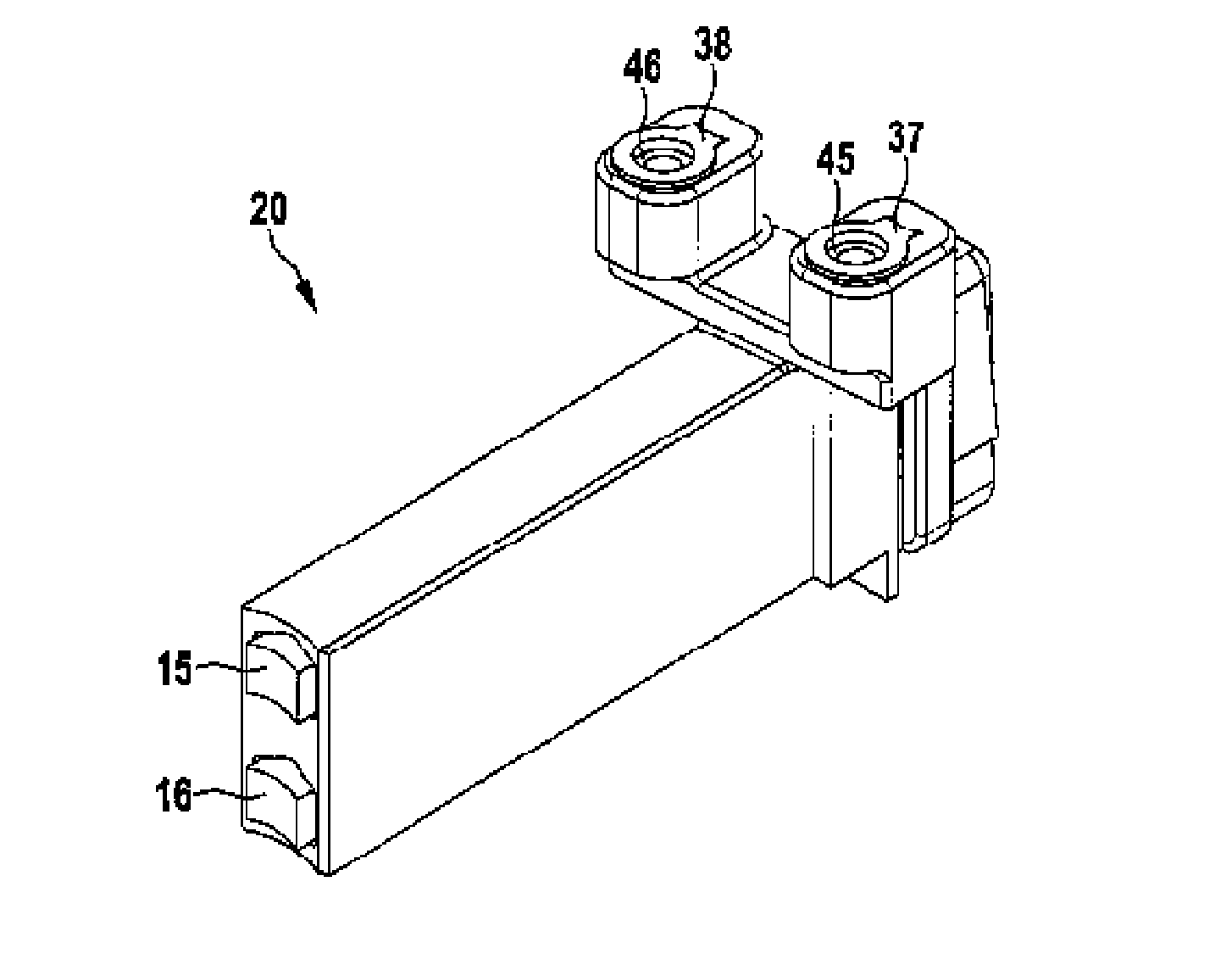
[0040]FIG. 4 shows the brush holder 20 in a In the case of this embodiment, the contacts 37 and 38 are aligned in such a way that, after assembly of the brush holder 20 in the guiding recess 27 has taken place, the screws 33 and 34 are aligned with their longitudinal axes in the axial direction. As already stated above, the contacts 37 and 38 are formed as nuts, so that the screws 33 and 34 can be screwed into them.

second embodiment

[0041]FIG. 5 shows the brush holder 20. In the case of this embodiment, the contacts 37 and 38 are configured without an internal thread, while the contacts 35 and 36 of the electronics unit 18 have an internal thread. In this embodiment, the screws 33 and 34 are first led through the contacts 37 and 38 and then screwed to the contacts 35 and 36 of the electronics unit 18.

third embodiment

[0042]FIG. 6 shows the brush holder 20. Here, the electrical connection between the brushes 15 and 16 and the electronics unit 18 is established via a plug-in connection 41.

[0043]FIG. 7 shows a schematic view of the brush holder 20 in a specific design corresponding to the embodiment according to FIGS. 1 to 4. All that can be seen is the brush 15 with a contact area 42, which is concavely formed and via which the brush 15 enters into electrical connection with the slip ring 13. In the brush holder 20, each brush 15 or 16 is assigned the spring element 21 or 22, respectively, which urges the corresponding brush 15 or 16 in the direction of the respective slip ring 13 or 14. The spring element 21 is formed as a spiral spring and receives inside it the line 23, via which the brush 15 is in electrical connection with the contact 37. It goes without saying that the same applies correspondingly to the brush 16 and the spring element 22. The lines 23 and 24 are fastened on their side facin...


PUM


Abstract

An electrical machine (1) with a machine housing (5) receiving an electrically excited rotor (2) and a stator (10) of the electrical machine (1) and with an electronics unit (18) fastened to the machine housing (5) and electrically connected to an exciter winding (3) of the rotor (2) via at least one sliding contact (11, 12) consisting of at least one slip ring (13, 14) assigned to the rotor (2) and at least one brush (15, 16) assigned to the electronics unit (18), the brush (15, 16) being arranged displaceably in a brush holder (20). In this case it is provided that the brush holder (20) is fastened exchangeably in a guiding recess (27) of the electronics unit (18).

Description

BACKGROUND OF THE INVENTION[0001]The invention relates to an electrical machine with a machine housing receiving an electrically excited rotor and a stator of the electrical machine and with an electronics unit fastened to the machine housing and electrically connected to an exciter winding of the rotor via at least one sliding contact consisting of at least one slip ring assigned to the rotor and at least one brush assigned to the electronics unit, the brush being arranged displaceably in a brush holder.[0002]Electrical machines of the type mentioned at the beginning are known from the prior art. The electrical machine has the rotor and the stator, which are arranged at least partly in the machine housing. The electrical machine is activated by means of the electronics unit. This means that it is electrically connected to the rotor and / or the stator of the electrical machine, in order to feed electrical current to the exciter winding of the rotor and / or an exciter winding of the st...

Claims


Application Information

Patent Timeline
Patent Type & Authority Applications(United States)
IPC IPC(8): H02K13/00
CPCH02K13/003H02K5/141H02K19/365H01R39/26H01R39/38H01R39/39H01R39/41H02K5/14H02K5/145H02K5/148
Inventor SCHROEDER, BERNDLUBINA, ZELJKOGESELLMANN, MATTHIASMAUER, CORNELIA
Owner ROBERT BOSCH GMBH
Why Eureka
Try Eureka