


Quick Research
Generate reliable direction feasibility study reports for your R&D in just a few steps.

Technical Q&A
Discover and master advanced knowledge NOW. Basics, ideas, possibilities, all at once.

Find Solutions
As an expert in R&D theories, this can generate solutions to your technical problems instantly.

Evaluate Feasibility
Analyze your overall solution with one click, know your potential R&D risks in advance.

Monitor Landscape
Get weekly tech updates, stay abreast of the latest tech innovations and key insights.
Brakes for mobile medical device
a mobile medical device and brake technology, applied in the field of wheeled chairs, can solve the problems of difficult use of one or more aspects of chairs, and achieve the effects of convenient storage, improved ease of use, and convenient entry and exi
- Summary
- Abstract
- Description
- Claims
- Application Information
AI Technical Summary
Benefits of technology
Problems solved by technology
Method used
Image

Examples
first embodiment
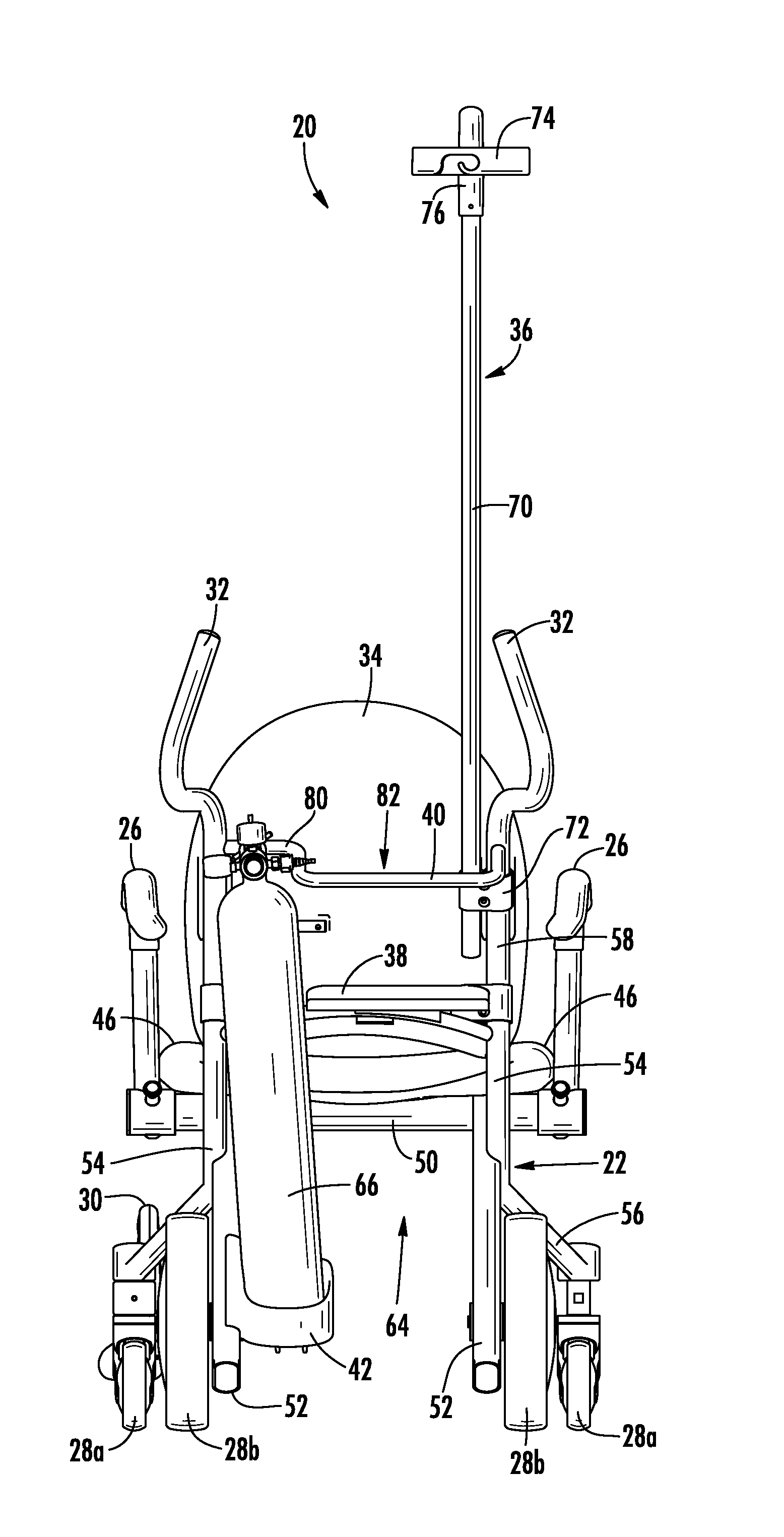
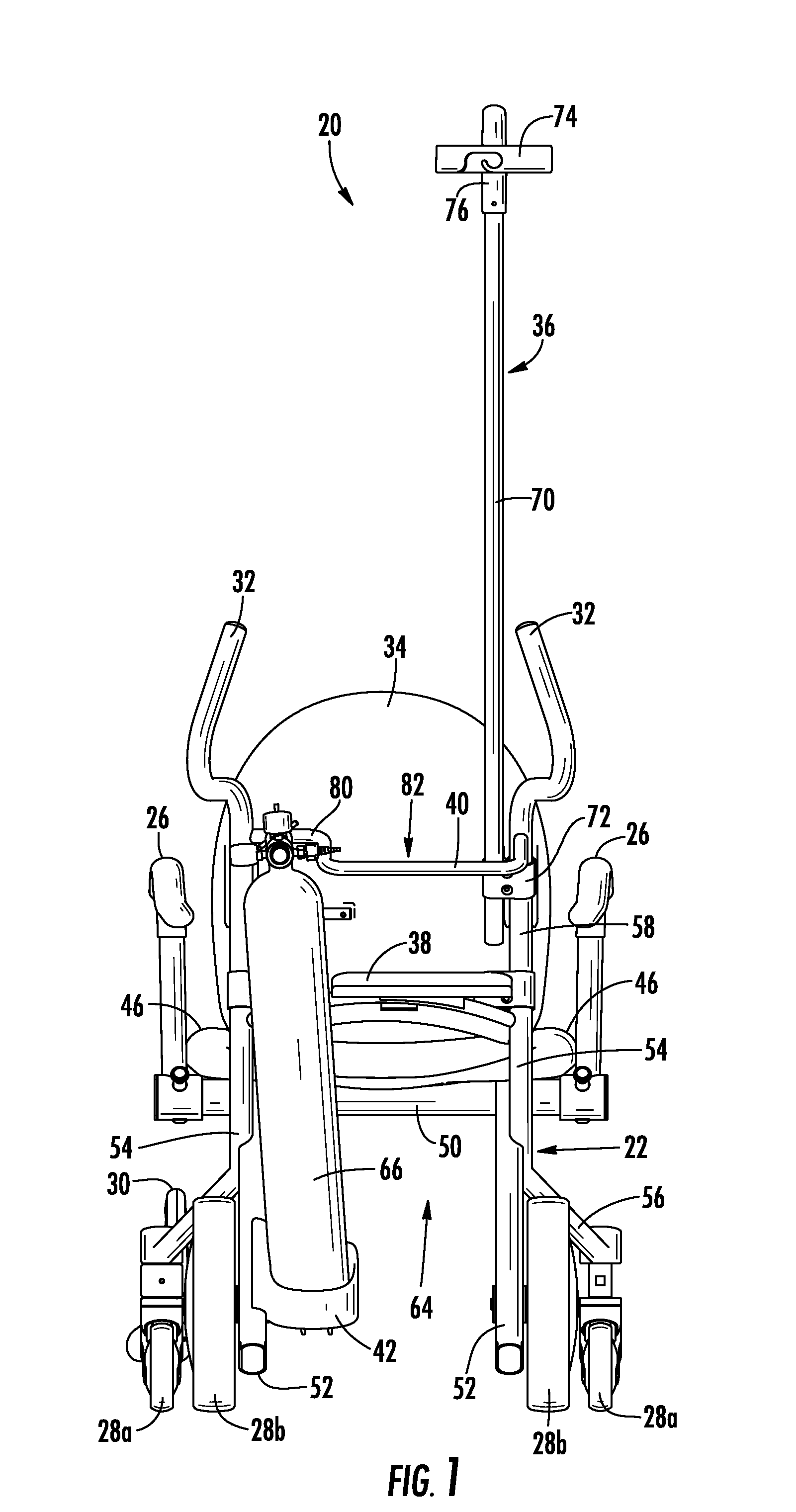
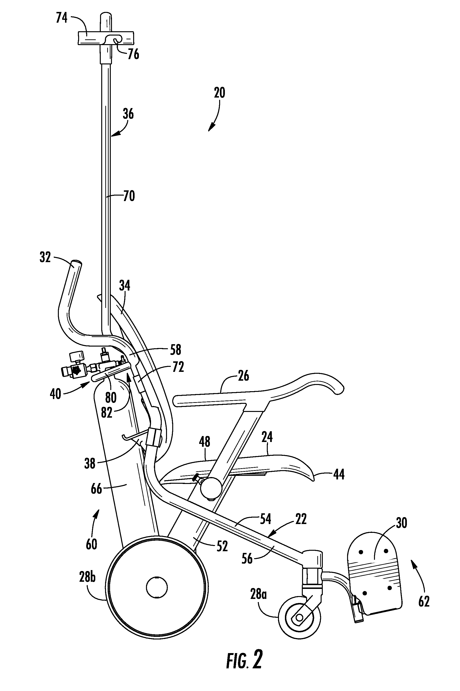
[0085]A transport chair 20 according to the invention is depicted in FIGS. 1-3. Transport chair 20 is adapted to allow a patient to be transported to different locations within a healthcare facility, such as, but not limited to a hospital, nursing home, doctor's office, or similar location. A number of different embodiments of transport chair 20 are described below and in the accompanying drawings. It will be understood that further variations of the embodiments described herein and shown in the accompanying drawings may be made without departing from the principles disclosed herein. It will also be understood that the wheeled transport chairs described herein include multiple innovative aspects and features, and that any one or more of these aspects and / or features may be combined together with any one or more of the other aspects or features, or that any one of these aspects or features may be used alone. For example, the following description includes a discussion of a variety of...
third embodiment
[0102]FIGS. 11-13 depict a transport chair 420 that includes many of the same aspects and components as transport chairs 20 and 220. Those components of transport chair 420 that are the same as those of transport chair 20 or 220 are labeled with the same reference numbers, and the description of those components applies equally to transport chair 420. Those components of transport chair 420 that do not have an analogue in transport chair 20 will bear a new reference number. It will further be understood that transport chair 420 may be modified to exclude any of its components that are lacking from chair 20 or chair 220, and / or it may be modified to include any of the components of chair 20 or 220 that it is shown to lack in FIGS. 11-13.
[0103]The armrests 26 of chair 420 may be incorporated into any of the chair embodiments described herein, including transport chairs 20 and 220, as well as any of the transport chairs subsequently described herein. Armrests 26 each include a support ...
embodiment 820
[0209]FIGS. 61-65 illustrate the ability of a transport chair embodiment 820 to nest with another similar transport chair 820. Transport chair 820 is similar to the other transport chairs described herein, and they all have the same nesting ability as transport chair 820. Those components of transport chair 820 that are the same as those of the other transport chairs described herein are labeled with the same reference numbers, and the description of those components applies equally to transport chair 820. This nesting ability is facilitated by the overall configuration of the transport chairs (820 and other embodiments) wherein the front end of the chair is generally wider than the rear end of the chair. By having the front end of the chair more expansive than the rear end, the front end of a first chair is able to fit around the more narrow rear end of a second chair, thereby allowing them to nest together. Further, as has been noted already, by having the front end more expansive...
PUM
 Abstract
Description
Claims
Application Information
 - R&D Engineer
- R&D Manager
- IP Professional
- Industry Leading Data Capabilities
- Powerful AI technology
- Patent DNA Extraction
Browse by: Latest US Patents, China's latest patents, Technical Efficacy Thesaurus, Application Domain, Technology Topic, Popular Technical Reports.
© 2024 PatSnap. All rights reserved.Legal|Privacy policy|Modern Slavery Act Transparency Statement|Sitemap|About US| Contact US: help@patsnap.com