
Trip mechanism and electrical switching apparatus including a trip member pushed by pressure arising from an arc in an arc chamber

a technology of trip mechanism and electrical switching apparatus, which is applied in the direction of circuit-breaking switch for excess current, protective switch details, protective switch operating/releasing mechanism, etc., can solve the problem of increasing the load of the trip latch during excessive current flow

Active Publication Date: 2013-06-06
EATON INTELLIGENT POWER LIMITED
View PDF1 Cites 12 Cited by
  • Summary
  • Abstract
  • Description
  • Claims
  • Application Information

AI Technical Summary

Benefits of technology

The patent text describes a device that helps prevent the mechanism of a tripping switch from getting overloaded due to the flow of electric current. The device uses a cylindrical piston to overcome the mechanical load caused by the magnetic forces generated on the switch's operating mechanism during the current flow. The technical effect of this invention is to ensure the safe and reliable operation of the tripping switch.

Problems solved by technology

During an interruption event, the trip latch load is increased during excessive current flow because of magnetic forces generated on the operating mechanism and the movable contact arms.
As a result, during a relatively high fault current, the trip solenoid must either have sufficient operating force to operate the trip latch lever, or the desired trip might be delayed or inhibited, which would be completely undesirable.

Method used


Image

  • Trip mechanism and electrical switching apparatus including a trip member pushed by pressure arising from an arc in an arc chamber
  • Trip mechanism and electrical switching apparatus including a trip member pushed by pressure arising from an arc in an arc chamber
  • Trip mechanism and electrical switching apparatus including a trip member pushed by pressure arising from an arc in an arc chamber

Examples


Embodiment Construction

[0021]As employed herein, the term “number” shall mean one or an integer greater than one (i.e., a plurality).

[0022]As employed herein, the statement that two or more parts are “connected” or “coupled” together shall mean that the parts are joined together either directly or joined through one or more intermediate parts. Further, as employed herein, the statement that two or more parts are “attached” shall mean that the parts are joined together directly.

[0023]The disclosed concept is described in association with a circuit breaker, although the disclosed concept is applicable to a wide range of electrical switching apparatus.

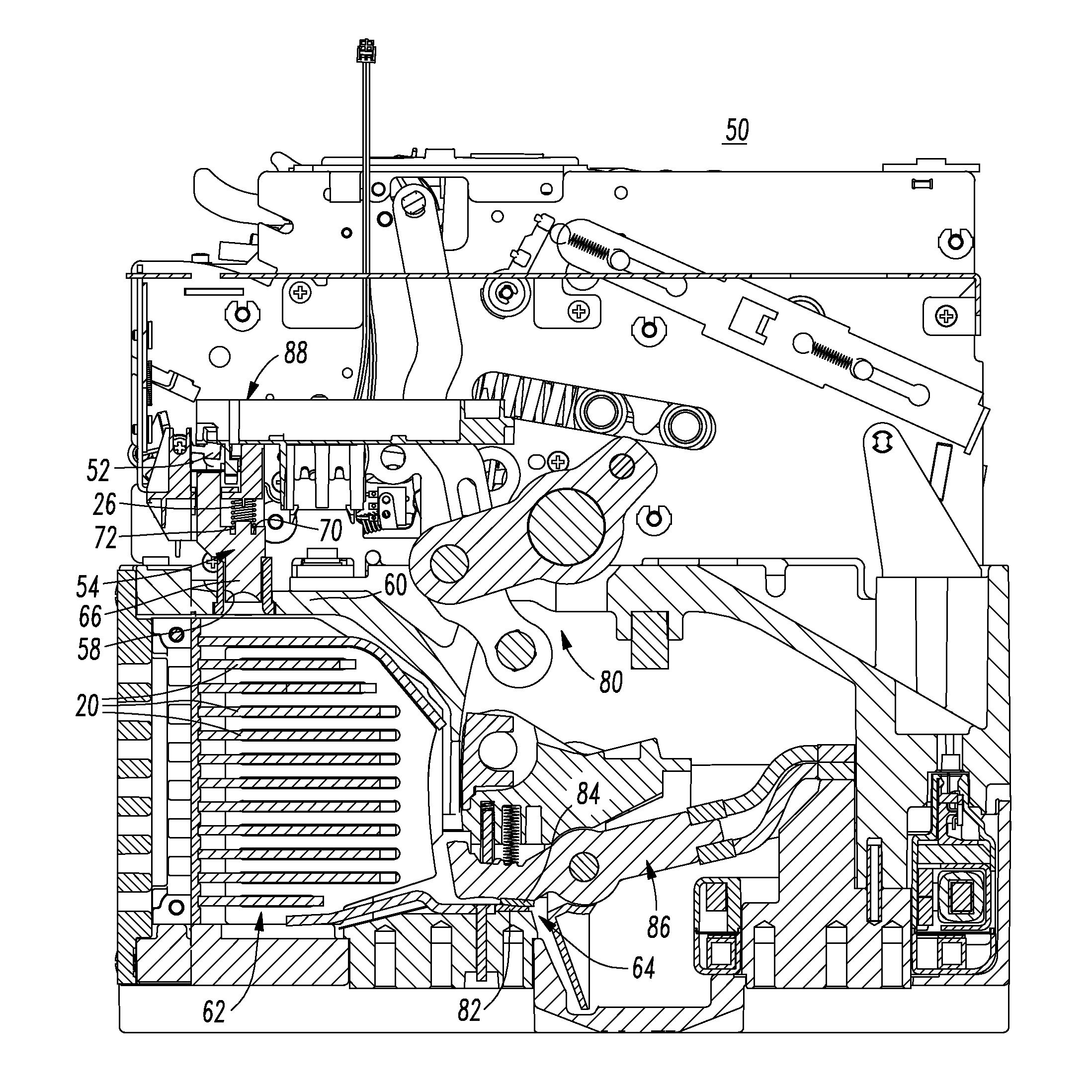
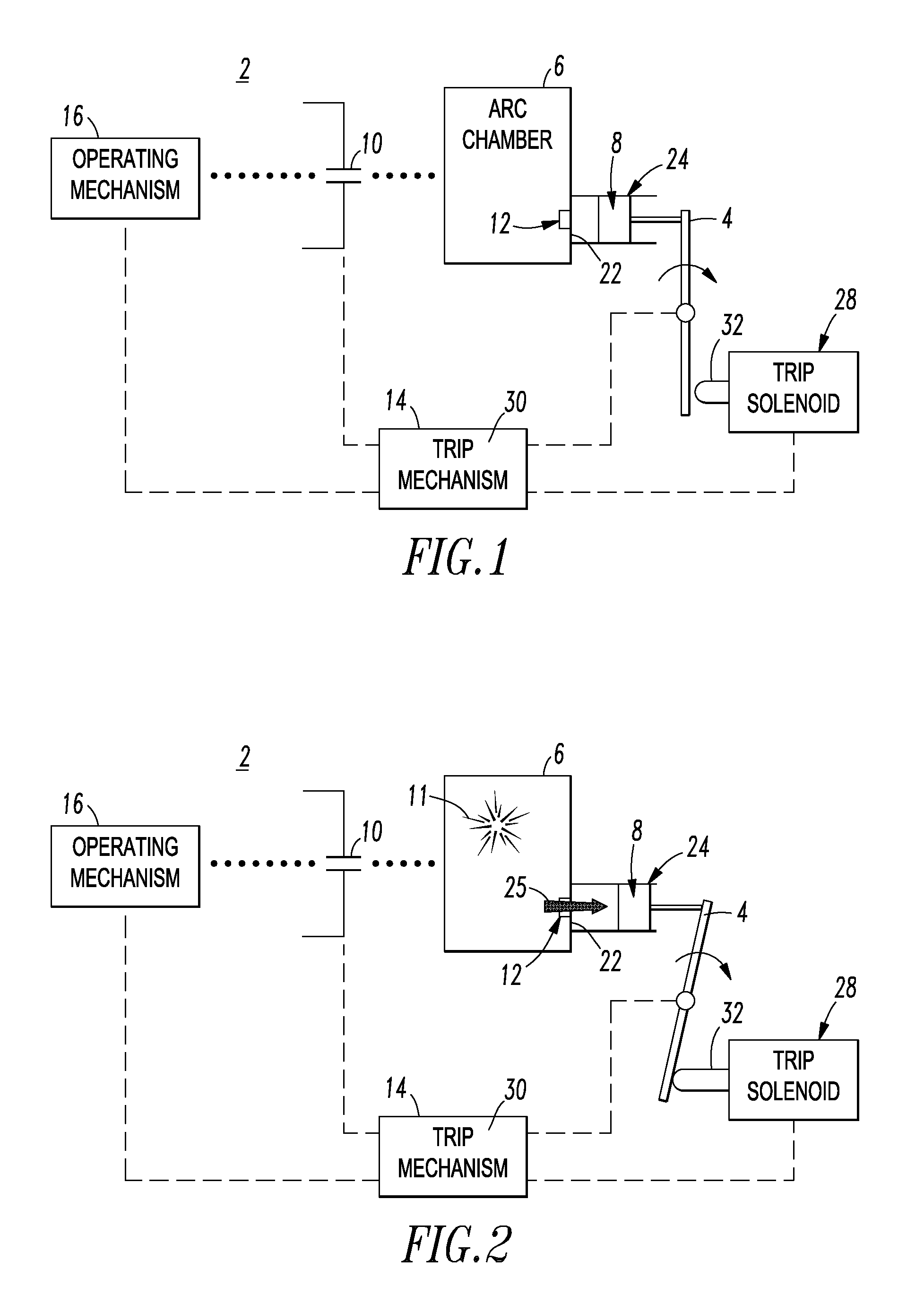
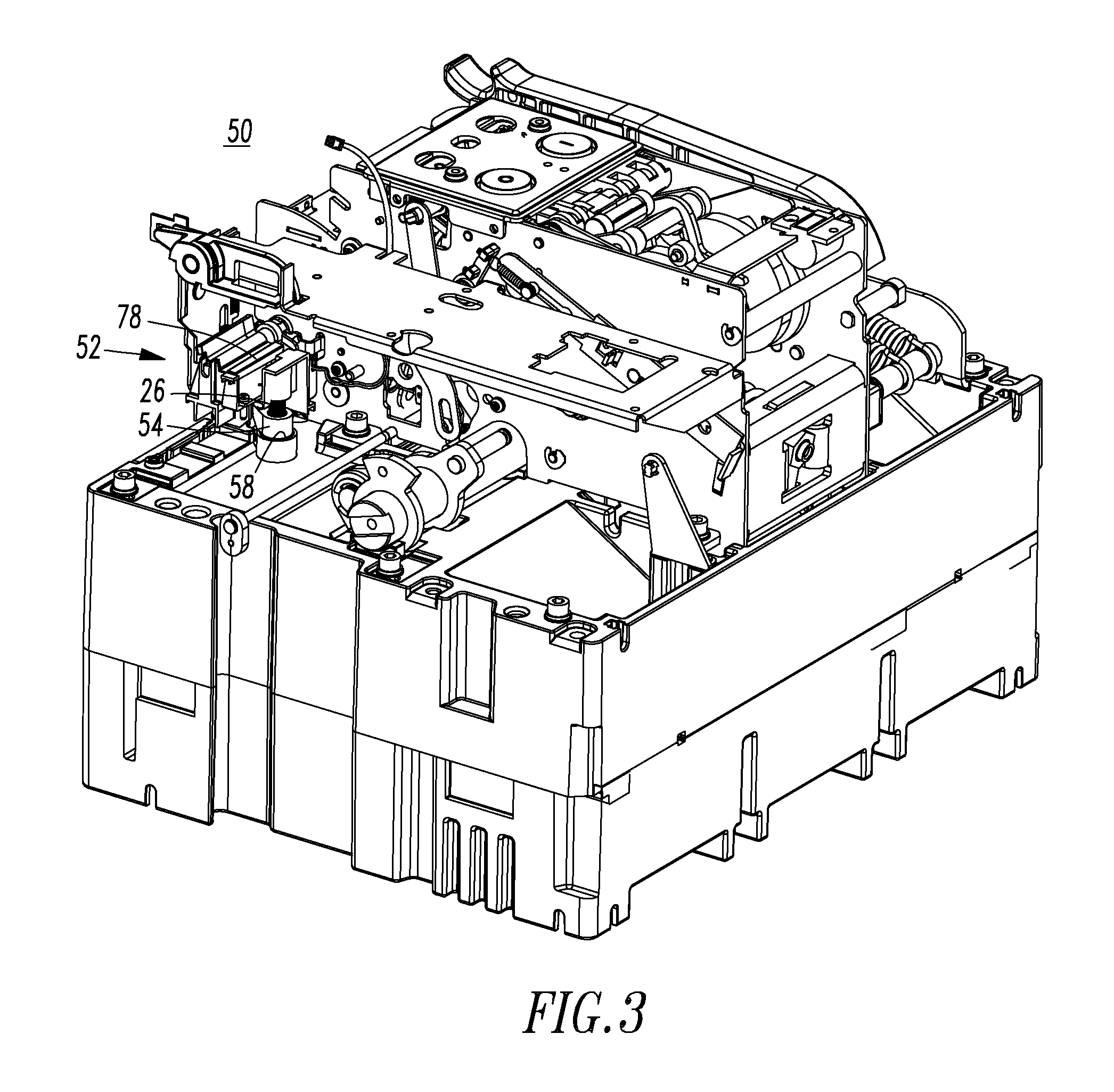
[0024]Referring to FIGS. 1 and 2, an electrical switching apparatus, such as a circuit interrupter (e.g., without limitation, the example circuit breaker 2), includes a trip latch, such as the example trip latch lever 4, an arc chamber 6 and a trip member 8 shown in respective non-tripped and tripped positions. During interruption of current flowing through sep...


PUM


Abstract

An electrical switching apparatus includes separable contacts, an operating mechanism structured to open and close the separable contacts, and a trip mechanism cooperating with the operating mechanism to trip open the separable contacts. The trip mechanism includes a trip latch, and an arc chamber operatively associated with the separable contacts. The arc chamber includes a plurality of arc plates and a barrier disposed between the arc plates and the trip latch. The barrier has an opening therein. A trip member is disposed in or about the opening of the barrier of the arc chamber. During interruption of current flowing through the separable contacts, pressure arising from an arc in the arc chamber pushes the trip member away from the barrier of the arc chamber to engage the trip latch and cause the trip mechanism to trip open the separable contacts.

Description

BACKGROUND[0001]1. Field[0002]The disclosed concept relates generally to electrical switching apparatus and, more particularly, to electrical switching apparatus, such as circuit breakers. The disclosed concept also relates to trip mechanisms for electrical switching apparatus.[0003]2. Background Information[0004]Electrical switching apparatus, such as circuit breakers, provide protection for electrical systems from electrical fault conditions such as, for example, current overloads, short circuits, abnormal voltage and other fault conditions. Typically, circuit breakers include an operating mechanism which opens electrical contact assemblies to interrupt the flow of current through the conductors of an electrical system in response to such fault conditions as detected, for example, by a trip mechanism, such as a trip unit.[0005]Latches are an important part of electrical switching apparatus, such as circuit breakers. A latch assembly typically includes three components: a pivotable...

Claims


Application Information

Patent Timeline
Patent Type & Authority Applications(United States)
IPC IPC(8): H01H33/08
CPCH01H9/342H01H2077/025H01H2071/2427H01H71/12
Inventor SHEA, JOHN J.SCHALTENBRAND, BRIAN J.JANUSEK, MARK A.
Owner EATON INTELLIGENT POWER LIMITED
Learn More