
A method for reducing the maximum inrush current of a compressor system comprising multiple asynchronous electrical motors and a compressor system for implementing this method

Active Publication Date: 2020-04-16
CARRIER CORP
View PDF0 Cites 0 Cited by
  • Summary
  • Abstract
  • Description
  • Claims
  • Application Information

AI Technical Summary

Benefits of technology

The patent aims to reduce the maximum inrush current in a compressor system with multiple asynchronous electrical motors. The method and apparatus are designed to be cost-effective and easy to implement.

Problems solved by technology

This problem is compounded when the compressor system comprises several electrical motors operated simultaneously.
A drawback of this so-called inrush current is that the power delivery network must be designed in accordance with the expected value of the inrush current, which increases the cost and the complexity of the fixed infrastructure.
Also, in some instances, public utilities may impose limits on the value of the maximum inrush current that can be drawn from public power distribution networks for an installation of a given size.
However, the reduction of inrush current may not always be sufficient for some applications.
However, such solutions increase the cost and the complexity of the compressor unit and are therefore not satisfactory.
Additionally, the efficiency of the electrical motor at maximum speed may be significantly reduced.

Method used


Image

  • A method for reducing the maximum inrush current of a compressor system comprising multiple asynchronous electrical motors and a compressor system for implementing this method
  • A method for reducing the maximum inrush current of a compressor system comprising multiple asynchronous electrical motors and a compressor system for implementing this method
  • A method for reducing the maximum inrush current of a compressor system comprising multiple asynchronous electrical motors and a compressor system for implementing this method

Examples


Embodiment Construction

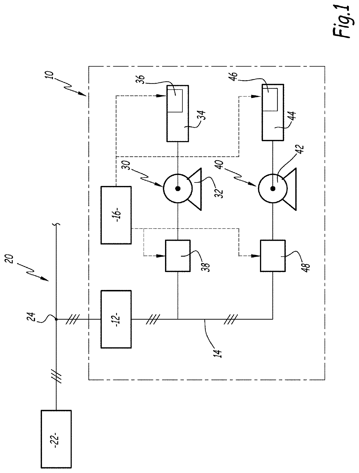
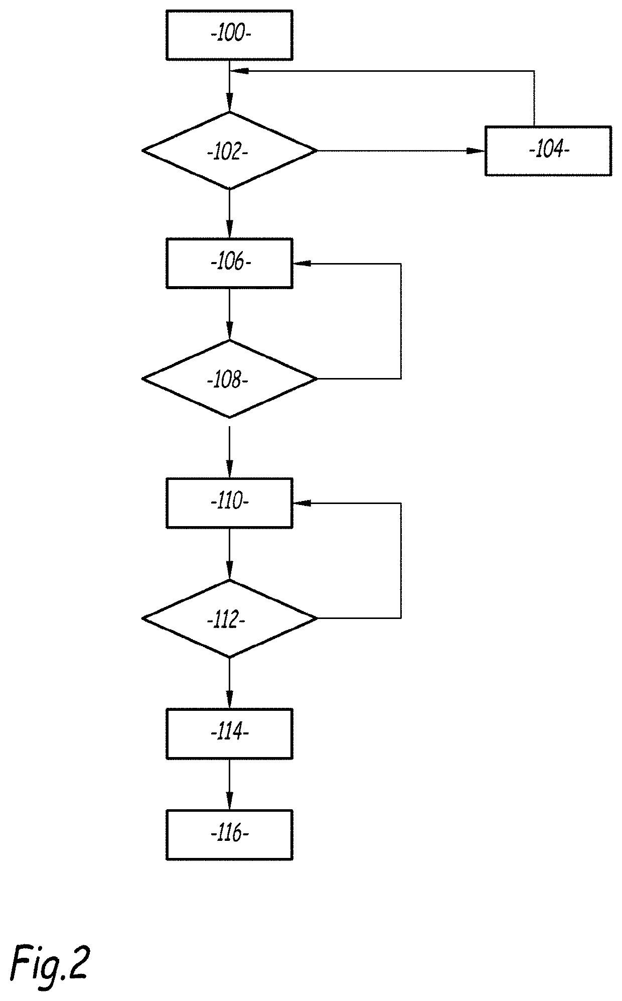
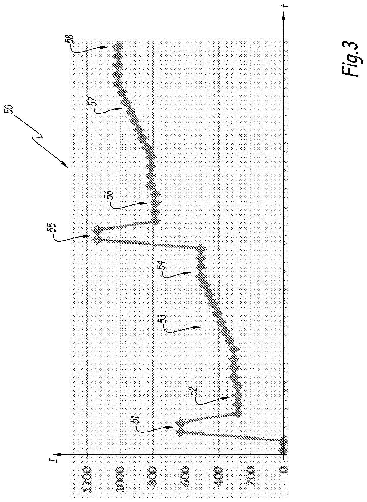
[0008]The object of the present disclosed embodiments is therefore to provide a compressor system and a method for controlling a compressor system comprising multiple asynchronous electrical motors for reducing the maximum inrush current, these method and apparatus being cost-effective and simple to implement.[0009]To that end, the disclosed embodiments relate to a method for controlling asynchronous electrical motors of a compressor system, this method comprising:[0010]receiving a command to start a first asynchronous electrical motor and a second asynchronous electrical motor of a compressor system;[0011]unloading said first and second motor, by operating respectively a first load control unit of the first motor and a second load control unit of the second motor, in order to reduce the mechanical load associated to said motors;[0012]starting the first motor and, only once the first motor is running at nominal speed, starting the second motor,[0013]loading both the first and second...


PUM


Abstract

This method for controlling asynchronous electrical motors of a compressor system, comprises: —receiving an order to start a first asynchronous electrical motor and a second asynchronous electrical motor of a compressor system; —unloading said first and second motors, by operating respectively a first load control unit of the first motor and a second load control unit of the second motor, in order to reduce the mechanical load associated to said motors; —starting the first motor and, only once the first motor is running at nominal speed, starting the second motor, —loading both the first and second electrical motor only once the second motor has started and is running at nominal speed, by operating the first load control unit and the second load control unit, in order to increase the mechanical load associated to said motors.

Description

TECHNICAL FIELD OF THE DISCLOSED EMBODIMENTS[0001]The disclosed embodiments relate to the operation of compressor units driven by asynchronous electric motors and, more generally, to a method for reducing the maximum inrush current of a compressor system comprising multiple asynchronous electrical motors. The invention also relates to a compressor system adapted to implement this method.BACKGROUND OF THE DISCLOSED EMBODIMENTS[0002]Compressor systems, such as chillers for domestic or industrial air-conditioned systems, include compressors that are driven by one or several electrical motors, such as asynchronous motors. These electrical motors are powered with a three-phase electrical current delivered by a power source through a power delivery network.[0003]Typically, when an asynchronous electrical motor is started up, the electrical current required to power the motor rises considerably with an amplitude that is several times higher than the full load amperage, i.e. the electrical ...

Claims


Application Information

Patent Timeline
IPC IPC(8): H02P1/58F25B49/02H02P1/26
CPCF25B2600/024F25B2600/026F25B2500/26F25B2400/075H02P1/26F25B49/022H02P1/58F25B49/025H02P1/32F25B2600/01F25B2600/23
Inventor BOVIO, STEFANO
Owner CARRIER CORP
Learn More