
Image forming apparatus

a technology of image forming apparatus and forming tube, which is applied in the direction of electrographic process apparatus, instruments, optics, etc., can solve the problems of productivity decline, achieve uniform hue stability, maintain productivity, and reduce the effect of adjusting operation

Inactive Publication Date: 2013-05-30
CANON KK
View PDF4 Cites 0 Cited by
  • Summary
  • Abstract
  • Description
  • Claims
  • Application Information

AI Technical Summary

Benefits of technology

The patent text describes a desire for an image forming apparatus that can perform efficient adjusting while keeping the colors stable and maintaining productivity. The technical effects of this invention include improved efficiency and hue stability, which can lead to higher productivity.

Problems solved by technology

However, in the above-mentioned method, the image forming condition adjusting operation is frequently performed, and productivity is decreased.

Method used


Image

  • Image forming apparatus
  • Image forming apparatus
  • Image forming apparatus

Examples


first embodiment

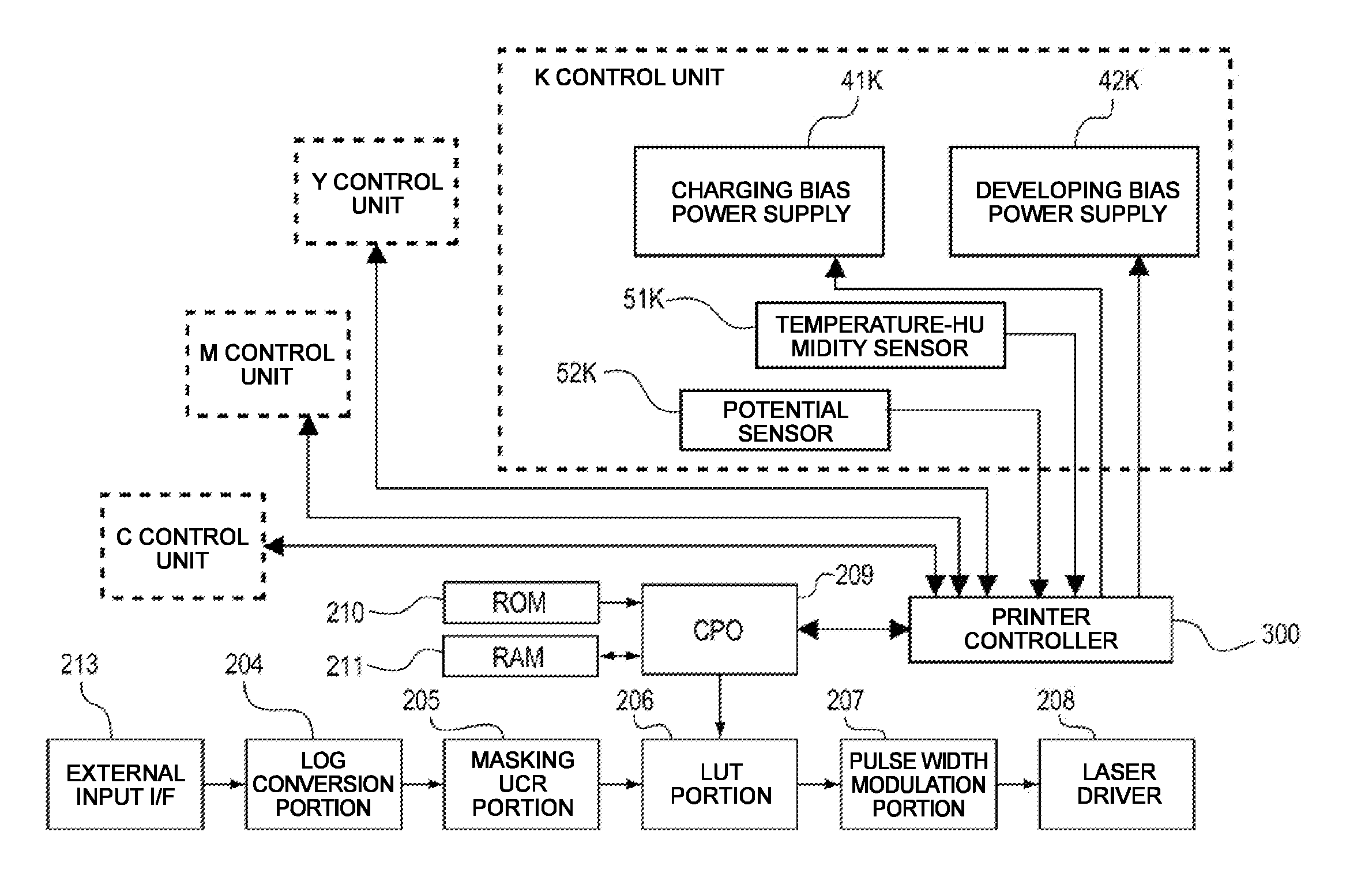
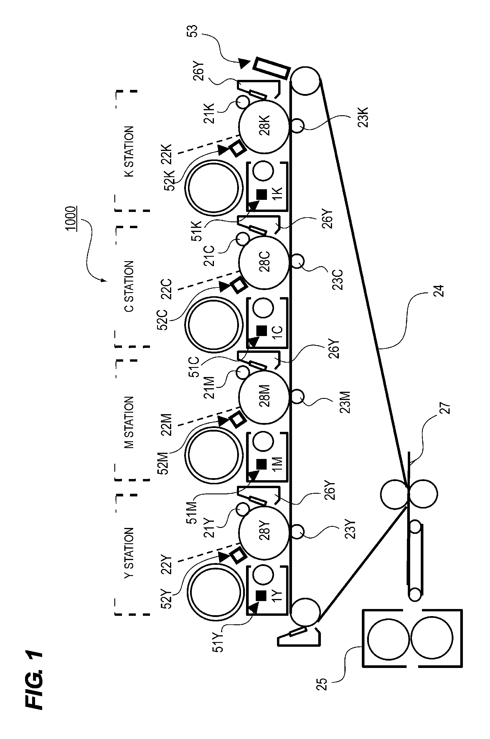
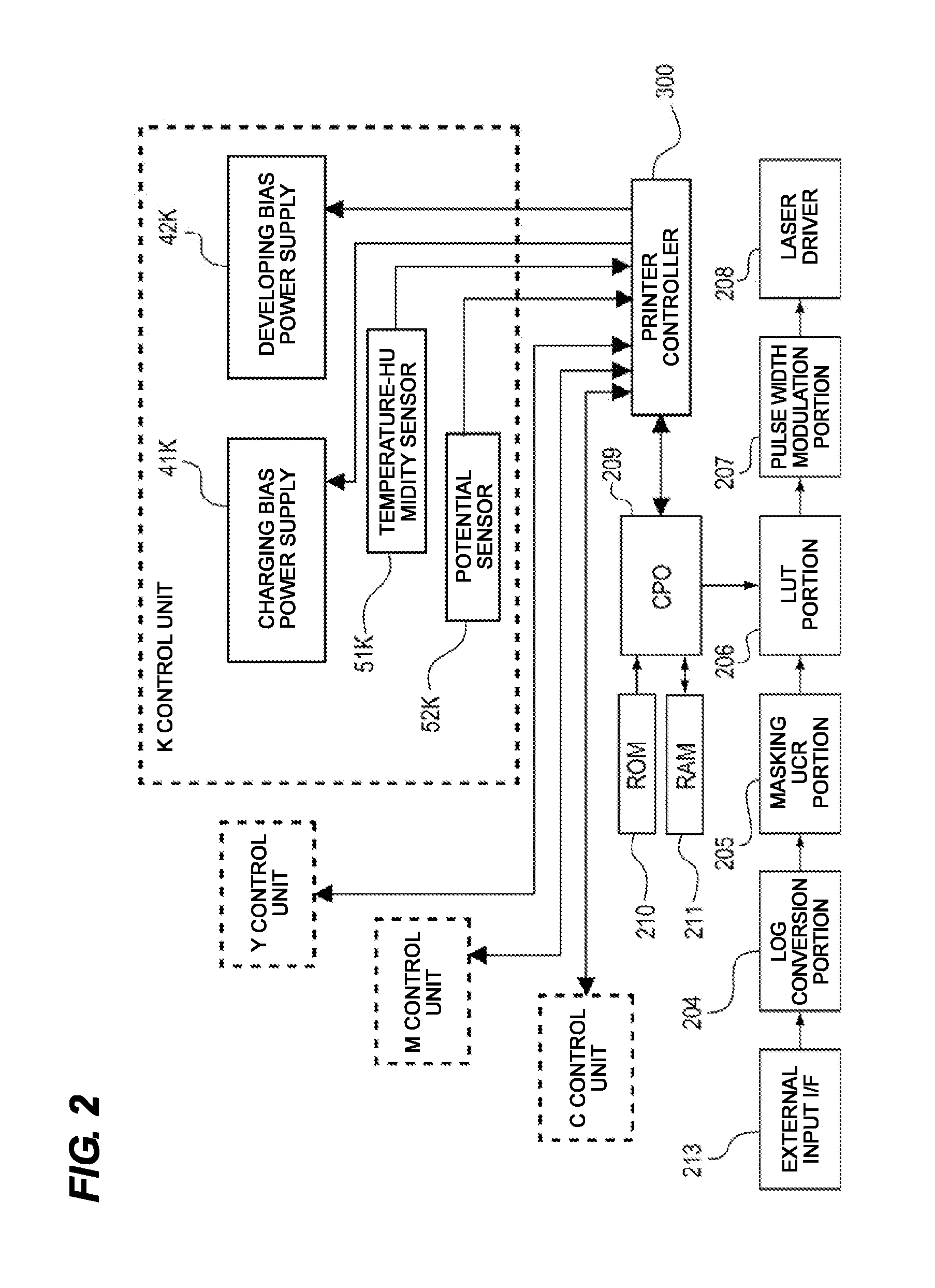
[0022]A first embodiment of an image forming apparatus according to the present invention will be described with reference to the accompanying drawings. FIG. 1 is a configuration view of an image forming apparatus 1000 according to the embodiment. As illustrated in FIG. 1, the image forming apparatus 1000 of the embodiment has respective stations of yellow, magenta, cyan, and black. In each of the stations, a charging bias in which an alternating current element overlaps a direct current element Vchg (V) is applied to primary chargers (image density adjusting apparatuses) 21Y to 21K from charging bias power supplies 41Y to 41K. Accordingly, surfaces of photoconductor drums (image bearing members) 28Y to 28K are charged with a white background portion potential Vd (V) by the primary chargers 21Y to 21K. In such an “AC charging type”, an alternating current element is adjusted such that a Vchg (V) value substantially becomes a Vd (V).

[0023]Then, electricity is removed through exposure...

second embodiment

[0052]Next, a second embodiment of an image forming apparatus according to the present invention will be described with reference to the accompanying drawings. Components overlapping the description of the first embodiment are designated by the same reference numerals, and the description thereof will be omitted.

[0053]The image forming apparatus of the embodiment performs gradation control, unlike the potential control of the image forming apparatus of the first embodiment. In addition, it is determined whether the gradation control is performed by force based on the humidity information RH, unlike the counter variable n of the first embodiment. Vchg of each of the stations of the image forming apparatus of the embodiment is −600 V, and Vdev is −450 V. Vd is −600 V, and V1 is −200 V.

[0054]FIG. 8 is a block diagram illustrating a system configuration of the image forming apparatus 1000 of the embodiment. As illustrated in FIG. 8, the printer controller 300 receives detection results ...


PUM


Abstract

An image forming apparatus includes photoconductor drums, a plurality of development apparatuses, temperature-humidity sensors that detects at least temperatures or humidity of the development apparatuses, image density adjusting units that adjusts an image density of the toner image, and a control unit that adjusts the image density of the toner image by the image density adjusting units based on detection results of the temperature-humidity sensors. The control unit controls the adjusting unit based on information about color differences of detection values of the temperature-humidity sensors so that the adjusting unit adjusts an image density of the toner image or not.

Description

BACKGROUND OF THE INVENTION[0001]1. Field of the Invention[0002]The present invention relates to an image forming apparatus for forming a color image using a plurality of color toners.[0003]2. Description of the Related Art[0004]A conventional image forming apparatus controls a primary charger such that a bright region and a dark region are formed on a photoconductor drum using the primary charger and an exposure unit, the potentials thereof are detected, and the detection values thereof converge on a preset target value (Japanese Patent Laid-open No. 7-261480).[0005]In addition, in another conventional image forming apparatus, a temperature-humidity sensor is installed at a development apparatus to recognize an environmental situation from moisture actually included in a developer. Then, highly precise feedback is performed and the developer is charged to a predetermined charging amount upon formation of an image, so that appropriate image formation is performed (Japanese Patent La...

Claims


Application Information

Patent Timeline
Patent Type & Authority Applications(United States)
IPC IPC(8): G03G15/00
CPCG03G15/0121G03G15/011G03G21/20G03G15/5037G03G15/0189
Inventor TANAKA, SHIGERU
Owner CANON KK
Learn More