
Apparatus and method for calculating filter coefficients for a predefined loudspeaker arrangement

a predefined loudspeaker and filter coefficient technology, applied in the field of wavefield synthesis systems, can solve the problems of significant audio quality decline, real but also virtual environment spatial sound reproduction quality, and the location of the loudspeaker, so as to improve the audio quality of audio signals reproduced by the predefined loudspeaker arrangement, reduce the computational effort for calculating the filter coefficient, and facilitate the calculation of the filter coefficients

Inactive Publication Date: 2013-05-30
IOSONO
View PDF5 Cites 5 Cited by
  • Summary
  • Abstract
  • Description
  • Claims
  • Application Information

AI Technical Summary

Benefits of technology

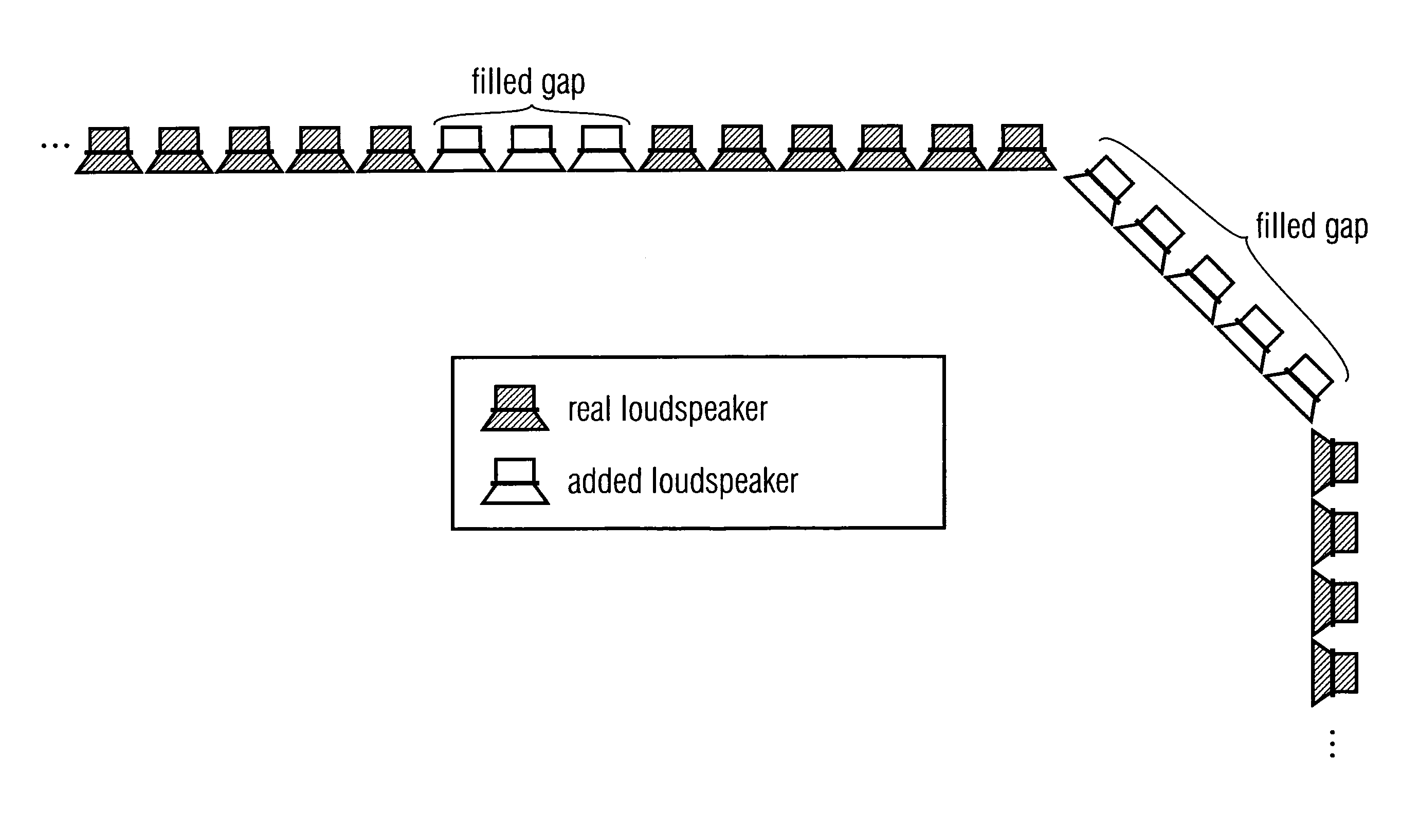
[0023]Embodiments according to the present invention are based on the central idea that filter coefficients determined for the different virtual loudspeaker arrangement are adapted for the predefined loudspeaker arrangements. Since the different virtual loudspeaker arrangement can be determined, for example, so that the calculation of the filter coefficients is easier than a calculation of filter coefficients for the predefined loudspeaker arrangement directly. In this way, the computational effort for calculating the filter coefficients may be significantly reduced. Further, the audio quality of audio signals reproduced by the predefined loudspeaker arrangement may be improved by adapting the filter coefficients for the virtual loudspeaker arrangement in comparison to loudspeaker arrangements reproducing the audio signals with the filter coefficients calculated for the predefined loudspeaker arrangement directly.

Problems solved by technology

In known audio systems, a significant weak point is the quality of the spatial sound reproduction of real but also virtual environments.
All common techniques have the disadvantage that both the location of the loudspeakers and the position of the listener are already imprinted in the transmission format.
If the loudspeakers are positioned in a wrong way with regard to the listener, the audio quality suffers significantly.
The acoustic impression matching the image is normally imprinted on the audio signal afterwards by manual operating steps in the so-called post production or is considered to be too expensive and too time-consuming to realize and is thus neglected.
This causes normally a discrepancy between individual sense impressions, which causes the designed space, i.e. the designed scene, to be considered as less authentic.
However, this is not possible every time, so that an incorrect reproduction may be caused.
If the actual arranged loudspeaker setup differs from the ideal arrangement, reproduction errors may appear, which may falsify, for example, a localization of the sound source reproduced by the system.
However, it may not be possible for real existing loudspeaker arrangements to represent the ideal loudspeaker positions.
For example, due to structural reasons, it may not be possible to locate loudspeakers at their ideal positions.
Occasionally, it is not possible at all to place parts of the loudspeaker arrangement.
Wave field synthesis device and method for deriving an array of loudspeakers.” However, the corresponding published calculation methods assume that the actual existing loudspeaker arrangement is used for the execution of the algorithm, although this arrangement might not be suitable for calculation since these algorithms do not provide handling for non-ideal loudspeaker placements or gaps in the speaker arrays.
The problem, that for the reproduction actual loudspeaker arrangements differ from an ideal arrangement, is made subject of discussion at various points and solutions are proposed.
Disadvantages of known methods are the high computational efforts for calculating the filter coefficients of the loudspeaker arrangements and / or a poor audio quality of reproduced audio signals.

Method used


Image

  • Apparatus and method for calculating filter coefficients for a predefined loudspeaker arrangement
  • Apparatus and method for calculating filter coefficients for a predefined loudspeaker arrangement
  • Apparatus and method for calculating filter coefficients for a predefined loudspeaker arrangement

Examples


Embodiment Construction

[0039]In the following, the same reference numerals are partly used for objects and functional units having the same or similar functional properties and the description thereof with regard to a figure shall apply also to other figures in order to reduce redundancy in the description of the embodiments.

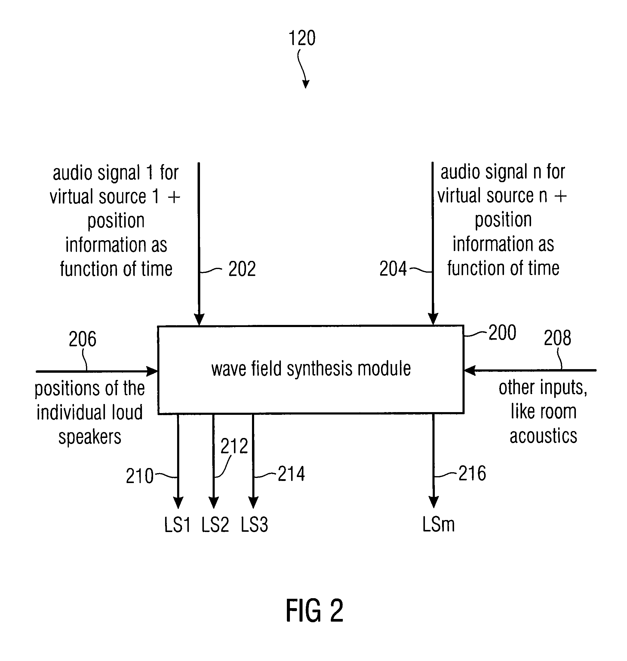
[0040]FIG. 1a shows a block diagram of an apparatus 100 for calculating filter coefficients for a predefined loudspeaker arrangement according to an embodiment of the invention, wherein the predefined loudspeaker arrangement comprises a plurality of loudspeakers. The apparatus 100 comprises a multi-channel renderer 120. The multi-channel renderer 120 calculates a filter coefficient for each loudspeaker of a virtual loudspeaker arrangement, being different from the predefined loudspeaker arrangement, based on properties of a virtual source of an audio object to be reproduced by the predefined loudspeaker arrangement. Further, the multi-channel renderer 120 determines an adapted filter ...


PUM


Abstract

An apparatus for calculating filter coefficients for a predefined loudspeaker arrangement has a multi-channel renderer. The multi-channel renderer calculates a filter coefficient for each loudspeaker of a virtual loudspeaker arrangement, being different from the predefined loudspeaker arrangement, based on a property (e.g. position or type) of a virtual source of an audio object to be reproduced by the predefined loudspeaker arrangement. Further, the multi-channel renderer determines an adapted filter coefficient for a loudspeaker of the predefined loudspeaker arrangement based on one or more calculated filter coefficients of one or more loudspeakers of the different virtual loudspeaker arrangement.

Description

CROSS-REFERENCE TO RELATED APPLICATIONS[0001]This application is a continuation of U.S. patent application Ser. No. 12 / 889,179, filed on Sep. 23, 2010, which claims priority from European Patent Application No. 10153467.5, which was filed on Feb. 12, 2010, and from U.S. Patent Application No. 61 / 245,064, which was filed on Sep. 23, 2009, all of which are incorporated herein by reference in their entirety.BACKGROUND OF THE INVENTION[0002]The present invention relates to wave-field synthesis systems and particularly to an apparatus and a method for calculating filter coefficients for a predefined loudspeaker arrangement.[0003]There is an increasing demand for new technologies and innovative products in the field of consumer electronics. Here, it is important prerequisite for the success of new multimedia systems to offer optimum functionalities or capabilities, respectively. This is achieved by the usage of digital technologies and particularly computer technology. Examples therefore ...

Claims


Application Information

Patent Timeline
Patent Type & Authority Applications(United States)
IPC IPC(8): H04R5/02
CPCH04S7/30H04R5/02H04S2420/13
Inventor STEFFENS, ROBERTMELCHIOR, FRANKDAUSEL, MARTINGRAEFE, ANDREAS
Owner IOSONO
Learn More