
Permanent magnet and method of producing permanent magnet

a permanent magnet and magnet technology, applied in the field of permanent magnets, can solve the problems of increasing material costs, affecting the magnetization of magnets, and significantly exceeding the natural abundance ratio of rare earth elements, so as to achieve the effect of reducing the production cost of the hybrid vehicle and increasing the output power of the hybrid vehicl

Active Publication Date: 2013-05-30
TOYOTA JIDOSHA KK
View PDF6 Cites 15 Cited by
  • Summary
  • Abstract
  • Description
  • Claims
  • Application Information

AI Technical Summary

Benefits of technology

The present invention provides a permanent magnet with metal grains that improve its coercivity. The metal grains are effectively diffused in the grain boundaries in the deep interior of the magnet. The magnet includes a main phase and a grain boundary phase, which is primarily composed of a first metal. A second metal that enhances the coercivity of the magnet and a third metal that has a lower standard free energy of oxide formation than the first and second metals are diffused in the magnet. The third metal forms an oxide in the grain boundary phase, allowing the second metal to diffuse into the deep interior of the grain boundary phase without forming an oxide. This results in a magnet with excellent coercivity.

Problems solved by technology

However, the amount of use of dysprosium or terbium as described above significantly exceeds the natural abundance ratio of rare-earth elements.
In addition, because the estimated reserves in commercially developed ore deposits are very small and because the ore deposits are unevenly distributed around the world, the necessity of element strategy has been recognized.
In addition, because dysprosium and terbium are rare metals, it is needless to say that it is necessary to reduce the amount of use of dysprosium or terbium as much as possible from the viewpoint of resource risk and material cost.
To diffuse dysprosium into the deep interior, it is necessary to use a large amount of dysprosium, resulting in an increase in the material cost.
When yttrium or the like is preliminarily present in the main phase of the permanent magnet described in JP-A-2002-190404, the magnetizing of the magnet may be greatly impaired if the yttrium or the like is not fully expelled from the main phase.

Method used


Image

  • Permanent magnet and method of producing permanent magnet
  • Permanent magnet and method of producing permanent magnet
  • Permanent magnet and method of producing permanent magnet

Examples


Embodiment Construction

[0049]A permanent magnet and a method of producing of the permanent magnet according to the present invention will be described below with reference to the drawings. It should be noted that the illustrated permanent magnet is a neodymium magnet but the permanent magnet of the present invention is also directed to any type of permanent magnet that has at least a main phase and a grain boundary phase as its structural components, such as samarium-cobalt magnet, samarium-iron-nitrogen magnet and praseodymium magnet.

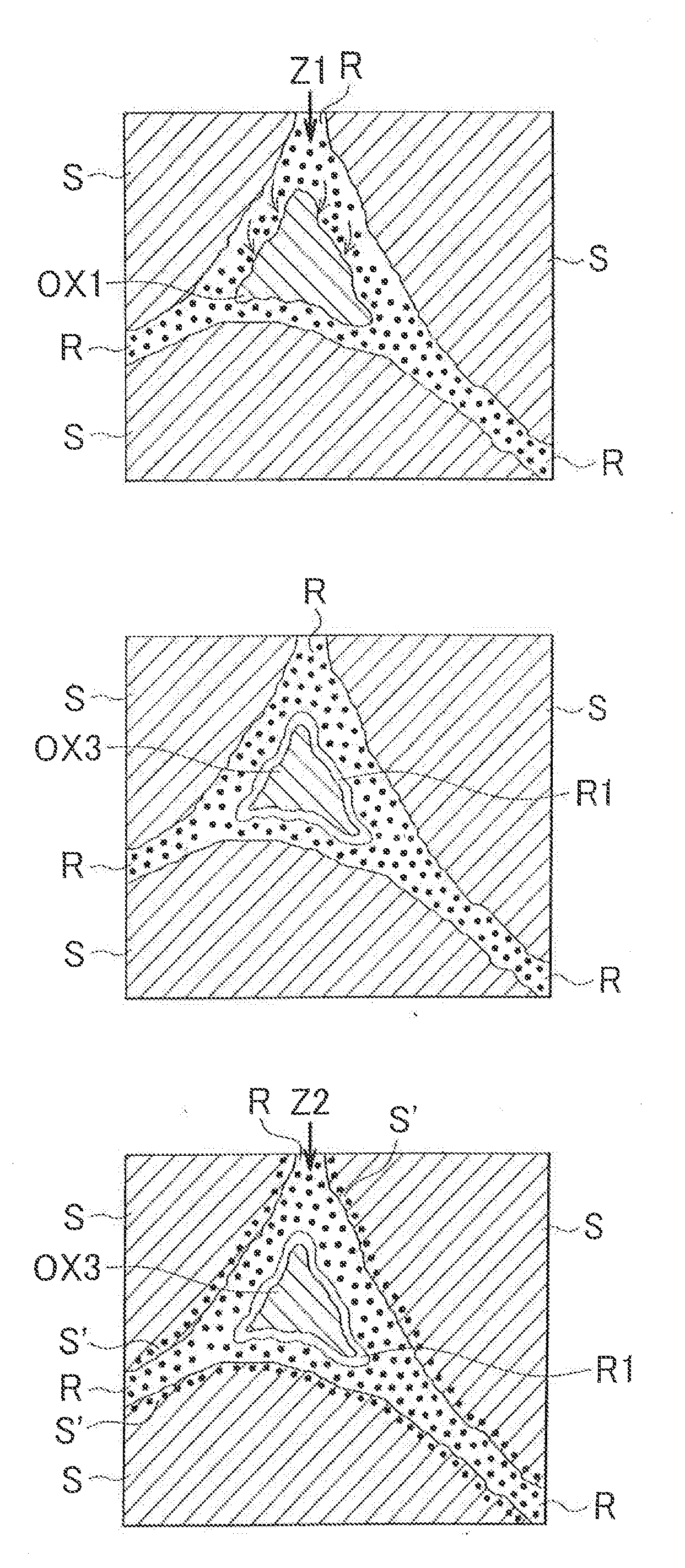
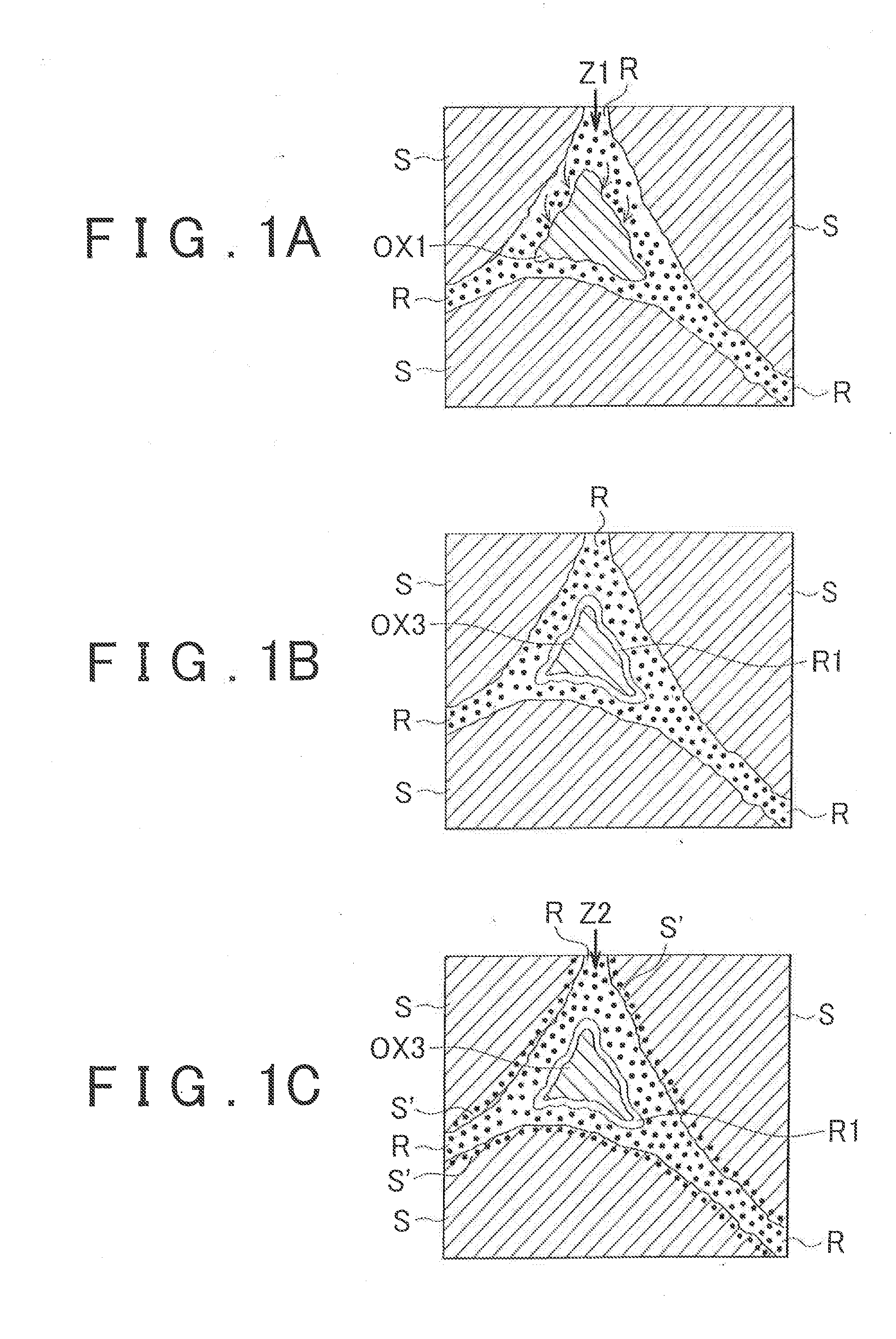
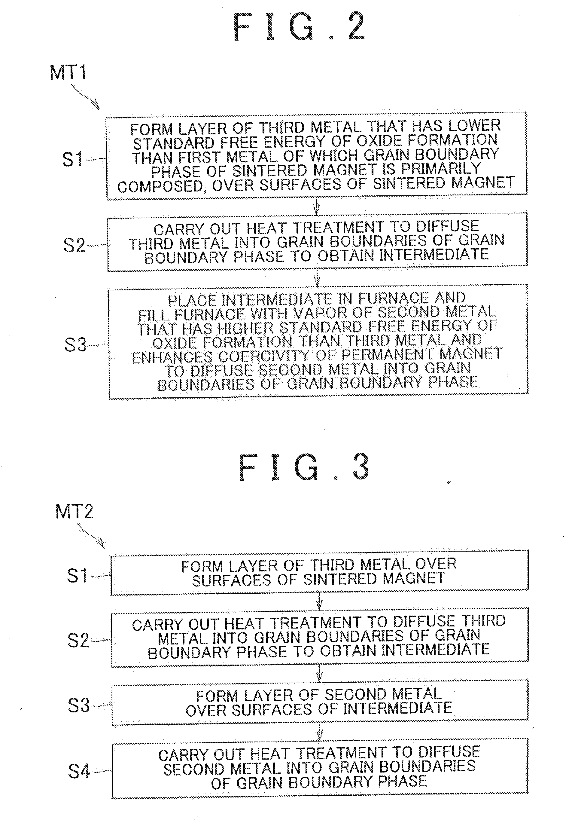
[0050]FIGS. 1A to 1C are grain structure diagrams that sequentially illustrate one embodiment of the method of producing a permanent magnet according to the present invention. Each of FIGS. 2 to 5 is a flow chart that shows an embodiment of the method of producing a permanent magnet according to the present invention.

[0051]The magnet shown in FIGS. 1A to 1C is an Nd—Fe—B sintered permanent magnet that is composed of a grain boundary phase R that contains neodymium as its mai...


PUM

PropertyMeasurementUnit
Percent by massaaaaaaaaaa

Abstract

A permanent magnet has a grain structure that includes a main phase and a grain boundary phase that is primarily composed of a first metal. A second metal that enhances the coercivity of the permanent magnet and a third metal that has a lower standard free energy of oxide formation than the first metal and the second metal are diffused in the permanent magnet, and the third metal is present in the form of an oxide in the grain boundary phase.

Description

BACKGROUND OF THE INVENTION[0001]1. Field of the Invention[0002]The present invention relates to a permanent magnet and a method of producing the permanent magnet.[0003]2. Description of Related Art[0004]Among motors including brushless DC motor, a motor that is provided with a permanent magnet embedded rotor that has a rotor core and a plurality of permanent magnets that are embedded in the rotor core (which is hereinafter referred to as “IPM motor”) is well known. For example, the IPM motor is used as a driving motor for hybrid vehicles.[0005]Making further reference to the permanent magnet that is used in actuators for motors or the like, neodymium magnets (also known as Nd—Fe—B sintered permanent magnets (such as Nd2Fe14B)) are finding wide application because of their excellent magnetic characteristics, and are used in vehicles including hybrid vehicles, which can be said to lead the current automobile industry; industrial machines, and wind power generators, which are attracti...

Claims


Application Information

Patent Timeline
IPC IPC(8): H01F1/01H01F41/00
CPCH01F1/0577H01F41/0293H01F41/005H01F1/01B22F3/10B22F3/26B22F5/00B22F2003/242B22F2003/248C22C38/002C22C38/005C22C38/06C22C38/10C22C38/16C23C14/16C23C14/34H01F1/0536H01F1/0557
Inventor MIYAMOTO, NORITAKAOMURA, SHINYA
Owner TOYOTA JIDOSHA KK
Learn More