
Power line voltage measurement using a distributed resistance conductor

a technology of distributed resistance and power line voltage, which is applied in the direction of resistor details, resistance/reactance/impedence, instruments, etc., can solve the problems of reducing the surrounding environment, high current through the resistive element, and endangering the surrounding environment (e.g., utility crews, pedestrians, etc., to achieve accurate measurement of electrical properties, facilitate power line management, and high resistance

Inactive Publication Date: 2013-05-30
TOLLGRADE COMM INC
View PDF0 Cites 9 Cited by
  • Summary
  • Abstract
  • Description
  • Claims
  • Application Information

AI Technical Summary

Benefits of technology

This patent describes a system that accurately measures the properties of power lines in a power distribution system. It uses sensors that are connected to the power lines using resistive elements. These elements have a high resistance along their length, which reduces the risk of large voltages causing high currents and potentially damaging the environment. The main technical effect of this system is improved power line management, reducing the risk of damage to both the environment and equipment.

Problems solved by technology

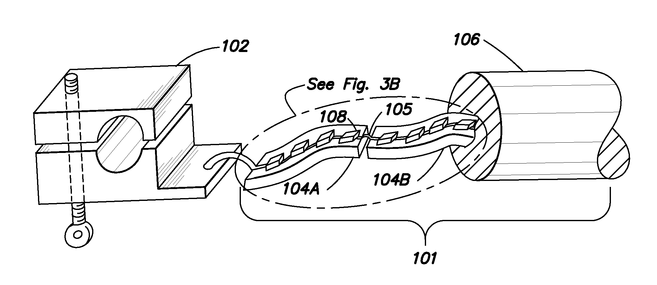
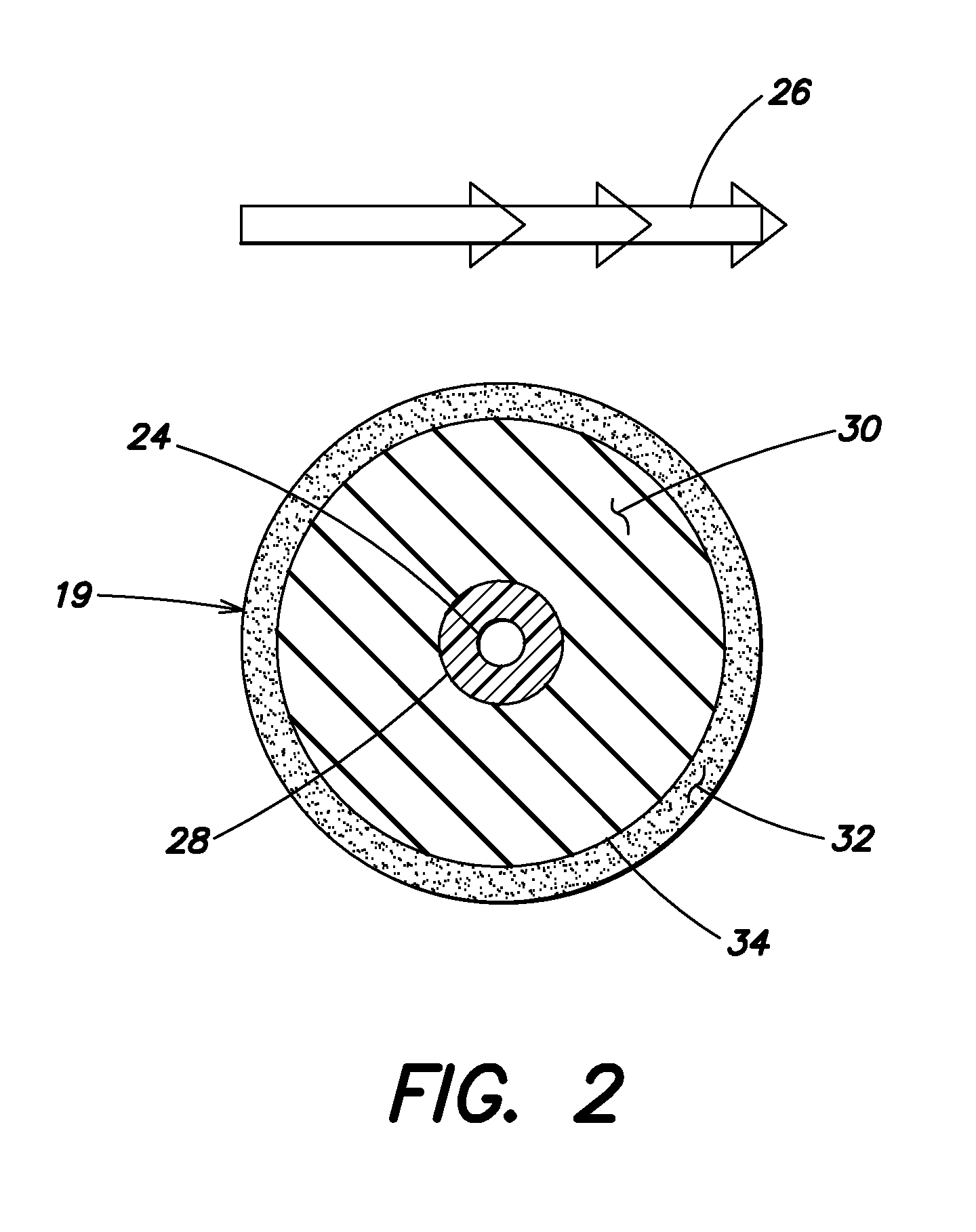
A resistive element having a distributed resistance may have a high resistance along its length such that if the resistive element were to sustain damage (e.g., by breaking, sagging, stretching, breaking away from the wire to which it is coupled, etc.), the risk of large voltages causing high currents through the resistive element and endangering the surrounding environment (e.g., utility crews, pedestrians, equipment, buildings, etc.) is reduced, even if the resistive element were to come in contact with an object in the environment.

Method used


Image

  • Power line voltage measurement using a distributed resistance conductor
  • Power line voltage measurement using a distributed resistance conductor
  • Power line voltage measurement using a distributed resistance conductor

Examples


Embodiment Construction

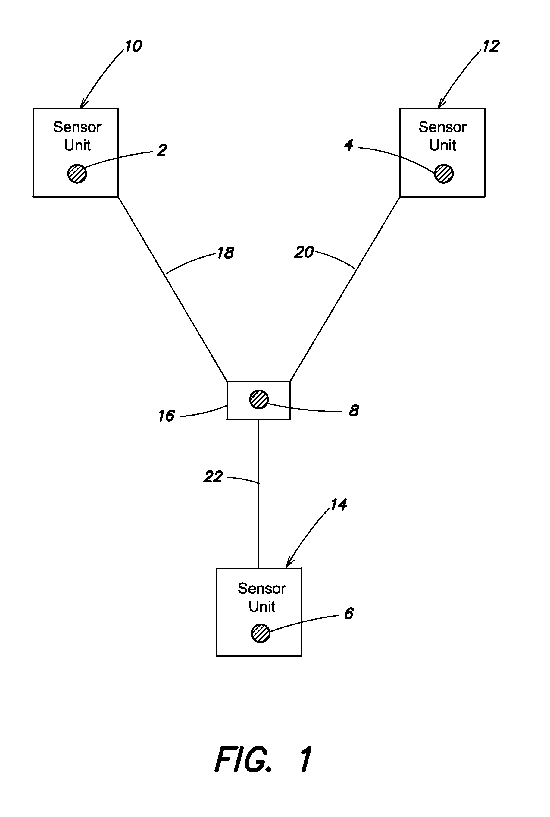
[0021]The inventors have recognized that improvements to the safety and simplicity of installation of sensor units in a power distribution system may, in addition to providing other benefits, increase the likelihood that such sensors will be deployed. With more widespread deployment, there is greater opportunity for benefits of monitoring of the power distribution systems. The inventors have recognized that improvements to safety and simplicity of installation may be achieved by using an element with distributed resistance to connect the sensor unit between wires of a power line. These improvements may allow for the installation of the sensor unit even when the power line is “hot.” Such an approach may also provide an increased ability to find faults in the power distribution system rapidly.

[0022]In a conventional approach using a metal wire to electrically couple a voltage sensor between two wires of a power line, if the connector were to become damaged by breaking (e.g., into two ...


PUM


Abstract

A system for measuring electrical properties of a power line comprising a first wire and a second wire. The system comprises a sensor unit configured for connection to the first wire; and an elongated resistive element comprising a first end configured for connection to the sensor unit and a second end configured for connection to the second wire, the elongated resistive element having a distributed resistance. The first wire may be a hot wire and the second wire may be a hot wire or a neutral wire.

Description

CROSS-REFERENCE TO RELATED APPLICATIONS[0001]The present application claims the benefit under 35 U.S.C. §119(e) of U.S. Provisional Application Ser. No. 61 / 565,087, filed on Nov. 30, 2011, titled “Power Line Voltage Measurement Using Distributed Resistance Conductor,” which is hereby incorporated by reference in its entirety.BACKGROUND[0002]Power lines are widely used in many settings to carry 50 Hz or 60 Hz alternating current to power the worldwide economy. They form an important part of the power distribution system, carrying power from generation facilities all the way to the locations where it is used. The power distribution system may include many types of power lines with high voltage lines used closer to the power generation facilities and lower voltage lines closer to the locations where the power is used such as homes and businesses, for example.[0003]A power company may desire to obtain accurate voltage measurements of power lines in the power distribution system in order...

Claims


Application Information

Patent Timeline
IPC IPC(8): H01C13/02H01C1/00H01C7/00G01R27/02
CPCH01C13/02G01R27/02G01R15/144H01C7/00G01R1/203H01C1/00
Inventor KIKO, FREDERICK J.NULTY, GREGORY M.
Owner TOLLGRADE COMM INC
Learn More