
Orthodontic Force Module Including Elastomeric Member for Class II and Class III Correction

a force module and orthodontic technology, applied in the field of orthodontics, can solve the problems of gradually diminishing force of coil springs after installation, and achieve the effects of preventing such injuries to patients, reducing the level of applied force, and retaining elasticity

Inactive Publication Date: 2013-05-23
ULTRADENT PROD INC
View PDF4 Cites 3 Cited by
  • Summary
  • Abstract
  • Description
  • Claims
  • Application Information

AI Technical Summary

Benefits of technology

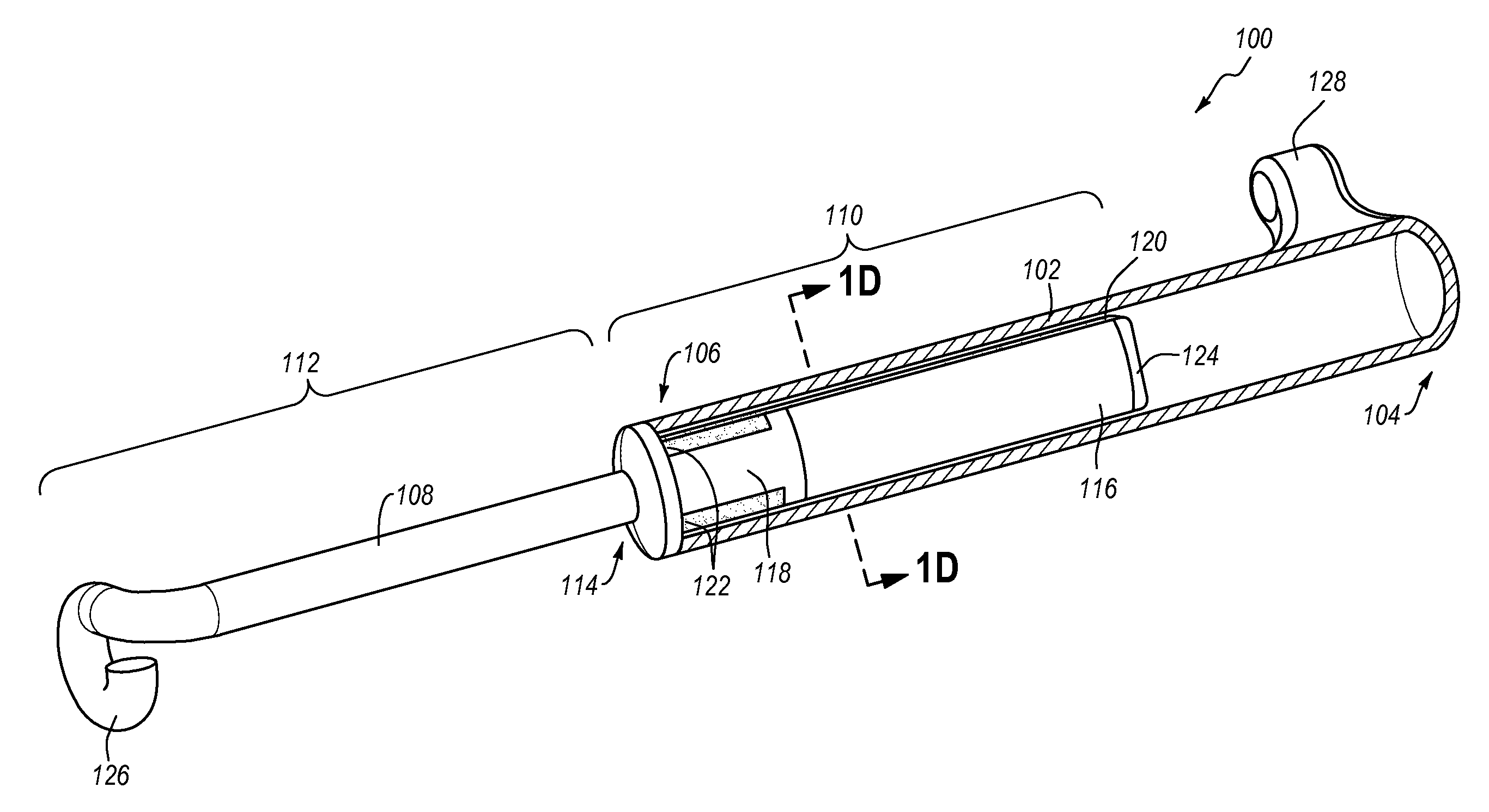
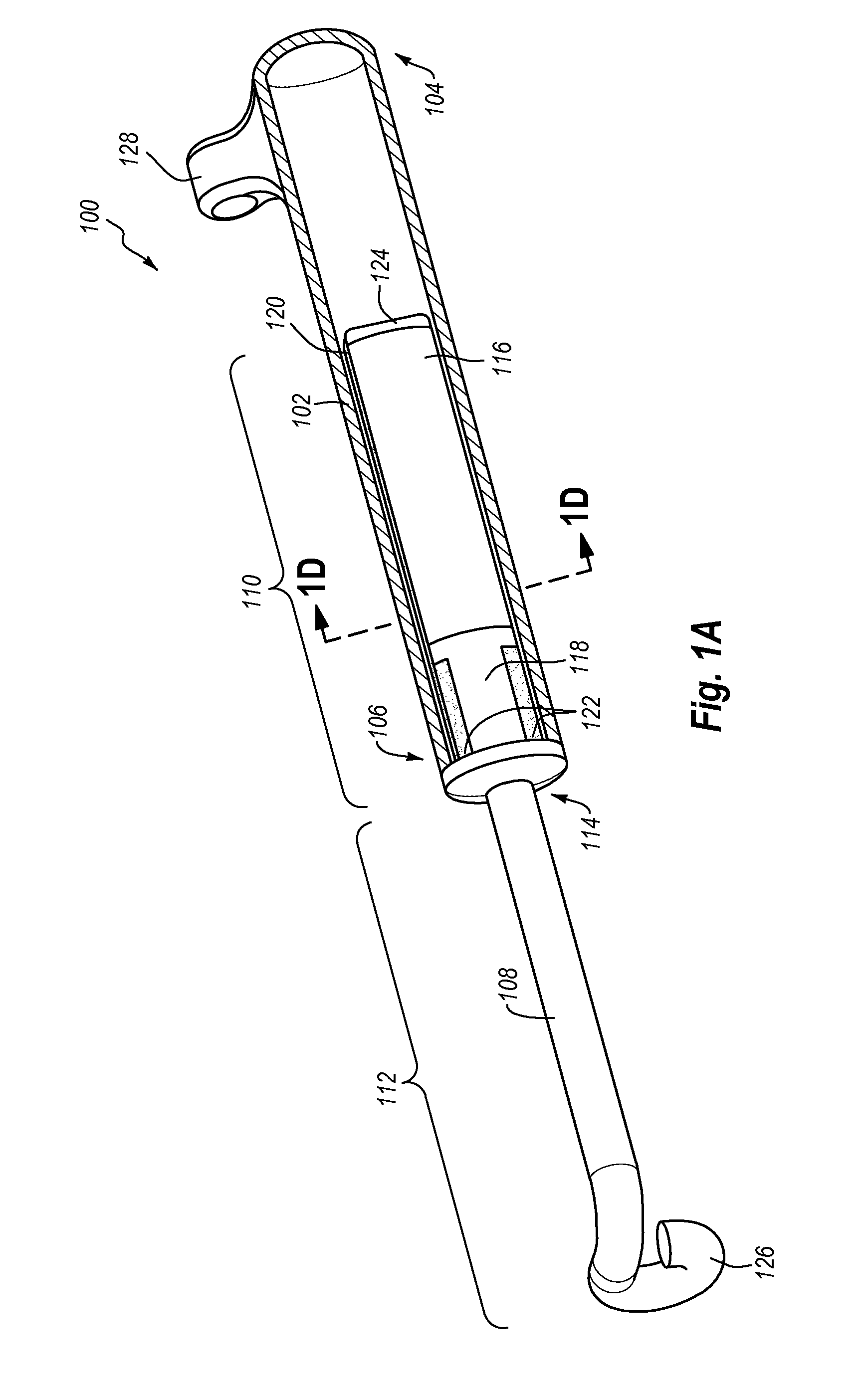
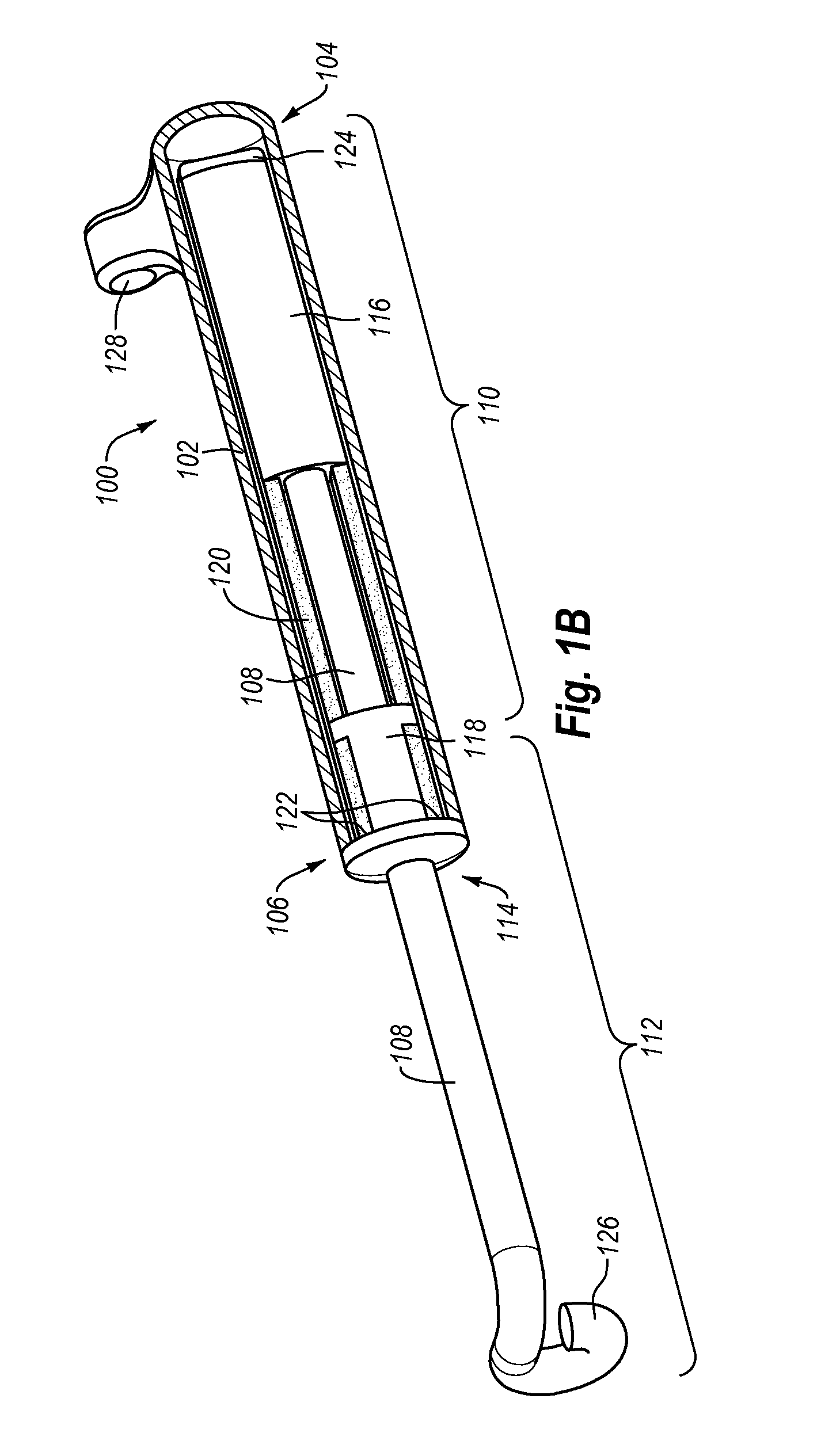
The present invention is an orthodontic force module for correcting dental malocclusions that uses an elastomeric member (e.g., silicone or thermoplastic elastomer) instead of a coil spring. The elastomeric member is more comfortable for the patient, as it does not pinch or poke the soft interior tissues of the mouth. The material retains its elasticity even in harsh environments within the oral cavity, allowing the force module to apply the desired level of force for movement of the jaw without any significant reduction in the level of applied force during treatment. The force module has an oval cross-section that minimizes discomfort to the patient and fits easily into the available space with minimal discomfort to the patient. The force module can also include a movable member and a force member disposed on or within the body that applies a counter-force to the movable member, whether it is made of elastomeric material or a coil spring. The use of an elastomeric member has been found to prevent injuries and reduce treatment time compared to devices that include a coil spring.

Problems solved by technology

For example, coil springs may exhibit a progressively diminishing level of force after installation.

Method used


Image

  • Orthodontic Force Module Including Elastomeric Member for Class II and Class III Correction
  • Orthodontic Force Module Including Elastomeric Member for Class II and Class III Correction
  • Orthodontic Force Module Including Elastomeric Member for Class II and Class III Correction

Examples


Embodiment Construction

I. Introduction

[0032]The present invention is directed to orthodontic force modules for use in correcting class II and / or class III malocclusions. In one embodiment, the force module includes an elongate body extending between a distal end and a proximal end; a movable member extending between a proximal end and a distal end that is slidably disposed relative to the elongate body; a movable piston disposed at or near the distal end of the movable member; a stop disposed at or near a proximal end of the elongate body and proximal to the movable piston; and an elastomeric member. A proximal end of the elastomeric member is cooperatively coupled to the stop, while a distal end is cooperatively coupled to the movable piston so that when the movable member is moved distally relative to the body, the elastomeric member stretches so as to apply a counter-force to the movable member.

[0033]When the force module is attached between teeth of the upper and lower jaw (e.g., for class II correcti...


PUM


Abstract

Orthodontic force modules for use in correcting class II and / or class III malocclusions. In one embodiment, the force module (100) includes an elongate body (102) extending between a distal end (104) and a proximal end (106), a movable member (108) extending between a proximal end (112) and a distal end (110) that is slidably disposed relative to the elongate body (102), a movable piston (108) disposed at or near the distal end (110) of the movable member, a stop (118) disposed at or near a proximal end (106) of the elongate body (102) and proximal to the movable piston (108), and an elastomeric member (120). A proximal end (112) of the elastomeric member (120) is cooperatively coupled to the stop (118), while a distal end (110) is cooperatively coupled to the movable piston (108) so that when the movable member is moved distally relative to the body, the elastomeric member (120) stretches so as to apply a counter-force to the movable member (108).

Description

BACKGROUND OF THE INVENTION[0001]1. The Field of the Invention[0002]The present invention is in the field of orthodontics, more particularly in the field of devices for correction of class II and / or class III malocclusions.[0003]2. The Relevant Technology[0004]Orthodontics is a specialized field of dentistry that involves the application of mechanical forces to urge poorly positioned or crooked teeth into correct alignment and orientation. Orthodontic procedures can be used for cosmetic enhancement of teeth, as well as medically necessary movement of teeth to correct overjets and / or overbites. For example, orthodontic treatment can improve the patient's occlusion, or enhanced spatial matching of corresponding teeth.[0005]The most common form of orthodontic treatment involves the use of orthodontic brackets and wires, which together are commonly referred to as “braces.” Orthodontic brackets are small slotted bodies configured for direct attachment to the patient's teeth or, alternati...

Claims


Application Information

Patent Timeline
IPC IPC(8): A61C7/36A61C7/00
CPCA61C7/00A61C7/36
Inventor LEWIS, PAUL E.
Owner ULTRADENT PROD INC
Learn More