Amplifier circuit

Active Publication Date: 2013-05-16
CIRRUS LOGIC INC
View PDF6 Cites 13 Cited by
  • Summary
  • Abstract
  • Description
  • Claims
  • Application Information

AI Technical Summary

Benefits of technology

This patent is about a circuit and method for controlling a switch that reduces the time it takes to transition between two states based on the input signal amplitude. The circuit includes a switch controller and an amplifier circuit with edge-filter circuitry. The method involves adjusting the time spent in each state based on the input signal amplitude. This can improve the efficiency and reliability of the switch.

Problems solved by technology

One issue with such a two-state Class-D amplifier is that for low signals the H-bridge output stage 101 will switch between the states A and B at a rapid rate to maintain a low output voltage.
Each transition between states will consume power, for example in charging and discharging the relatively large output MOS switch transistors.
This will lead to substantial ripple current in the load, especially for low load inductance, which will tend to cause power losses.
The large differential-mode voltage ripple across the load may also result in consequent EMI problems, especially if the load is somewhat distant from the driver amplifier, i.e. H-bridge output stage 101.
As the spurious signal contains harmonics of the output sine wave the actual output will also contain opposite harmonic components to cancel this spurious signal and thus harmonic distortion will appear across the load.
Also the common-mode modulation may cause generation of signal-dependent common mode EMI.
This may be inadequate in some applications which require a power supply rejection ratio in excess of 80 dB.

Method used


Image

  • Amplifier circuit
  • Amplifier circuit
  • Amplifier circuit

Examples


Embodiment Construction

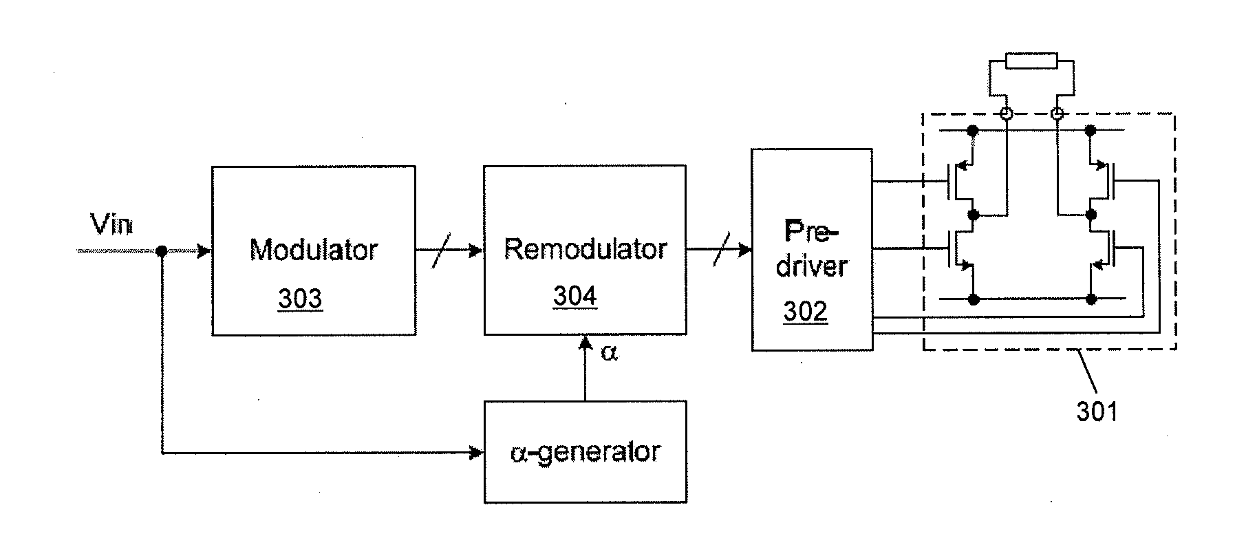
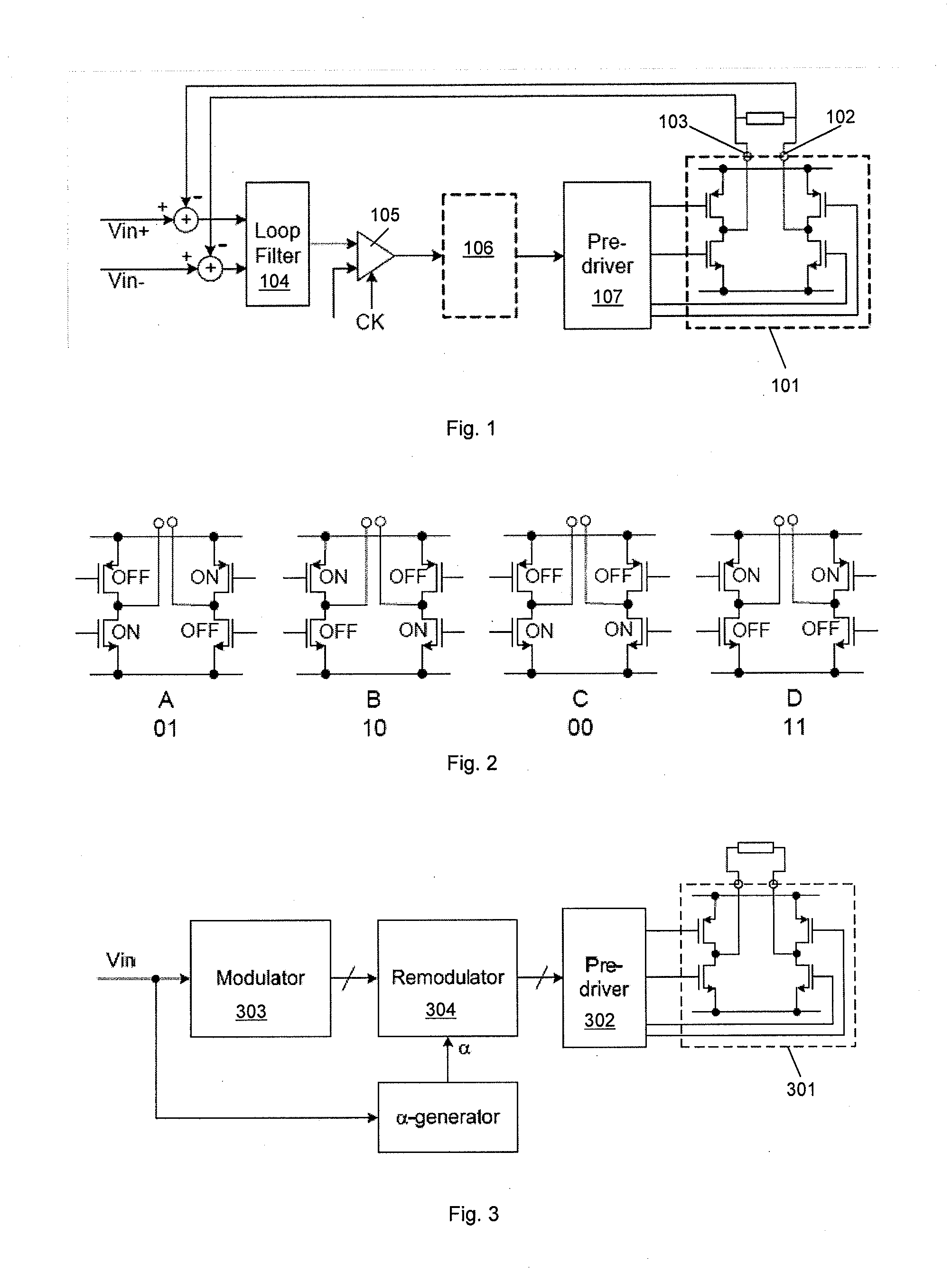
[0055]FIG. 3 illustrates the principles of a pulse-density-modulated Class-D amplifier according to an embodiment of the invention. It will be understood however that the principles may be applicable to any type of Class-D amplifier, which are sometimes referred to as sigma-delta amplifiers or switched amplifiers.

[0056]The amplifier arrangement shown in FIG. 3 has an H-bridge stage 301 which is driven by pre-driver circuitry 302 to be operable in each of the four states illustrated in FIG. 2. The amplifier comprises modulator circuitry 303 for receiving the input signal Vin and deriving a control signal indicative of which output state the H-bridge should be switched into. The modulator 303 may therefore comprise a three level comparator as described previously, or more generally any three level quantizer. Thus the output of the modulator may be, for example, a logic +1, 0 or −1 depending on the level input signal. It will be noted that FIG. 3 omits the feedback path discussed above...


PUM


Abstract

Class D amplifier circuits for amplifying an input signal. The amplifier has an H-bridge output stage and thus has switches for switchably connecting a first output to a first voltage, e.g. Vdd, or a second voltage (e.g. ground) and for switchably connecting a second output to the first or second voltages. A switch controller is configured to control the H-bridge stage so as to vary between a plurality of states including at least a first state in which the outputs are both connected to the first voltage and a second state in which the outputs are both connected to said second voltage. The switch controller is configured to vary the proportion of time spent in the first state relative to the second state based on an indication of the amplitude of the input signal. The amplifier may therefore have first circuitry for deriving a proportion value (α) based on the input signal (Din) and second circuitry for generating control signals for selecting the first state or said second state based on the proportion value (α).

Description

[0001]This application claims the benefit of U.S. Provisional Application No. 61 / 558,845, filed on Nov. 11, 2011, the disclosure of which is incorporated by reference in its entirety.BACKGROUND OF THE INVENTION[0002]1. Field of the Invention[0003]This invention relates to Class-D amplifier circuits, especially to Pulse-Density-Modulated or Sigma-Delta Class-D amplifiers with an H-bridge output.[0004]2. Description of the Related Art[0005]FIG. 1 shows a basic arrangement of a pulse-density-modulated (PDM) Class-D amplifier, sometimes referred to as a Sigma-Delta amplifier. An output stage 101 comprises four switches connected in an H-bridge arrangement between two supplies, typically a supply voltage Vdd and ground. Feedback signals from the output terminals 102 and 103 of the H-bridge are respectively subtracted from input signals Vin+ and Vin− of the amplifier in order to generate respective error signals which are passed through a loop filter 104, for example an integrator.[0006]T...

Claims


Application Information

Patent Timeline
IPC IPC(8): H03F3/217
CPCH03F3/2173
Inventor LESSO, JOHN PAUL
Owner CIRRUS LOGIC INC
Why Eureka
Try Eureka